Suzuki GSX-R 1000 Service Manual: DTC “c12” (p0335): ckp sensor circuit malfunction.
Detected condition and possible cause
|
Detected condition |
Possible cause |
| The signal does not reach ecm for 3 sec. Or more, after receiving the starter signal. |
|
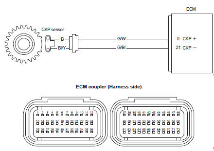
Wiring diagram
Troubleshooting
| Caution when using the multi-circuit tester, do not strongly touch the terminal of the ecm coupler with a needle pointed tester probe to prevent terminal damage. |
| Note after repairing the trouble, clear the dtc using sds tool. Refer to “use of sds diagnosis reset procedures” . |
|
Step |
Action |
Yes |
No |
|
1 |
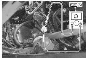
Special tool (a): 09900–25008 (multi circuit tester set) Tester knob indication resistance (Ω) Ckp sensor resistance 142 – 194 Ω (b – bl/y)
Special tool
Ckp sensor continuity ∞Ω¶ (infinity) (b . Ground, bl/y. Ground)
Are the resistance and continuity ok? |
Go to step 2. | Replace the ckp sensor with a new one. |
|
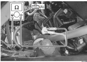
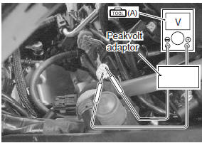
2 |
Special tool
Tester knob indication
voltage ( Ckp sensor peak voltage 0.5 V and more ((+) terminal: b – (–) terminal: bl/y)
Is the voltage ok? |
|
|
 (a): 09900–25008 (multi
 (a): 09900–25008 (multi
 )
)
 DTC “c11” (p0340): cmp sensor circuit
malfunction
DTC “c11” (p0340): cmp sensor circuit
malfunction
Detected condition and possible cause
Detected condition
Possible cause
The signal does not reach ecm for 3 sec. Or more, after
receiving the starter signal.
...
 DTC “c13” (p0105-h/l): iap sensor circuit
malfunction
DTC “c13” (p0105-h/l): iap sensor circuit
malfunction
Detected condition and possible cause
Detected condition
Possible cause
C13
Iap sensor voltage is not within the
following range.
0.5 V ≤ Sensor voltage &l ...
Other materials:
Engine oil and filter change
Change the engine oil and oil filter
at the scheduled times. The
engine should always be warm
when the oil is changed so the oil
will drain easily. The procedure is
as follows:
Place the motorcycle on the
side stand.
Remove the three screws of
the right fairing 1.
...
Rear combination light removal and installation
Removal
Remove the frame cover assembly. Refer to “exterior parts removal and
installation” in section 9d .
Remove the clamps (1).
Disconnect the combination light coupler (2).
Remove the rear combination light assembly (3).
Remove the combination light brack ...
Side-stand removal and installation
Removal
Support the motorcycle with a jack or wooden block.
Caution
do not support the motorcycle with the exhaust pipes.
Make sure that the motorcycle is supported securely.
Remove the side-stand as shown in the side-stand construction.
Refer to ...