Suzuki GSX-R 1000 Service Manual: DTC “c11” (p0340): cmp sensor circuit malfunction
Detected condition and possible cause
|
Detected condition |
Possible cause |
| The signal does not reach ecm for 3 sec. Or more, after receiving the starter signal. |
|
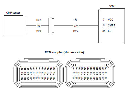
Wiring diagram
Troubleshooting
| Caution when using the multi-circuit tester, do not strongly touch the terminal of the ecm coupler with a needle pointed tester probe to prevent terminal damage. |
| Note after repairing the trouble, clear the dtc using sds tool. Refer to “use of sds diagnosis reset procedures” . |
|
Step |
Action |
Yes |
No |
| 1 |
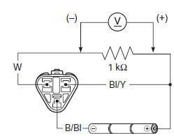
Special tool
Tester knob indication
voltage (
Is the voltage ok? |
|
|
 : 09900–25008 (multi circuit
 )
)
 Malfunction code and defective condition table
* : Immobilizer system equipped model only. ...
 DTC “c12” (p0335): ckp sensor circuit
malfunction.
DTC “c12” (p0335): ckp sensor circuit
malfunction.
Detected condition and possible cause
Detected condition
Possible cause
The signal does not reach ecm for 3 sec. Or more, after
receiving the starter signal.
...
Other materials:
Instrument panel
The fuel indicator light 8,12,13
Lcd's and tachometer needle
work as follows to confirm their
function when the ignition switch
is turned to the "on" position.
The fuel indicator light 8,12
and 13 come on for 3 seconds.
All lcd segments display for 3
seconds.
&nbs ...
Spark plug inspection and cleaning
Inspect spark plug
every 6 000 km (4 000 miles, 12 months)
Heat range
Remove the spark plugs. Refer to “ignition coil and spark plug removal
and installation” in section 1h .
Check spark plug heat range by observing electrode
color. If the electrode of the spark plug is wet
appe ...
Rear wheel components
Rear axel nut
Collar
Dust seal
Bearing
Retainer
Rear sprocket
Sprocket mounting drum
Wheel damper
Bearing
Spacer
Air valve
Rear wheel
Wheel balancer
Rear tire
Dust seal
Collar
Rear brake disc
Rear axle
1 ...