
Suzuki GSX-R 1000 Service Manual: Regulated voltage inspection
Inspect the regulated voltage in the following procedures:
- remove the front seat. Refer to “exterior parts removal and installation” in section 9d (page 9d- 6).
- Start the engine and keep it running at 5 000 r/min with the dimmer switch turned hi position.
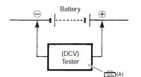
- Measure the dc voltage between the battery (+) and (–) terminals using the multi-circuit tester. If the voltage is not within the specified value, inspect the generator and regulator/rectifier. Refer to “generator inspection” and “regulator / rectifier inspection” .
| Note when making this test, be sure that the battery is in fully charged condition. |
Special tool
 (a): 09900–25008 (multi circuit
tester set)
Tester knob indication
voltage ( )
)
Regulated voltage (charging output) standard: 14.0 – 15.5 V at 5 000 r/min
- Install the front seat. Refer to “exterior parts removal and installation” in section 9d (page 9d- 6).
 Battery current leakage inspection
Inspect the battery current leakage in the following
procedures:
turn the ignition switch off.
Remove the front seat. Refer to “exterior parts
removal and installation” in section ...
 Generator inspection
Generator coil resistance
Remove the left side cowling. Refer to “exterior parts removal and
installation” in section 9d .
Disconnect the generator coupler (1).
Measure the re ...
Other materials:
Carrying a passenger
Before you invite someone to be a
passenger on your motorcycle,
you need to be thoroughly familiar
with motorcycle operation. Adjust
tire pressures and suspension
according to the tire pressure
and loading section and the suspension
section of this manual.
The passenger should always
hold ...
Excva adjustment
Inspect the excva operation and adjust it if necessary
in the following steps:
Step 1
Set the excva to the adjustment position. Refer to
“excv cable removal and installation” (page 1k-
6).
Step 2
Turn the ignition switch off.
Turn the mode select switch off.
Turn the ...
Special tools and equipment
Recommended service material
Note
required service material is also described in the following.
“Starter motor components”
Special tool
...