Suzuki GSX-R 1000 Service Manual: Generator inspection
Generator coil resistance
- Remove the left side cowling. Refer to “exterior parts removal and installation” in section 9d .
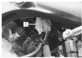
- Disconnect the generator coupler (1).
- Measure the resistance between the three lead
wires.
If the resistance is out of specified value, replace the stator with a new one. Also, check that the generator core is insulated properly.
| Note when making this test, be sure that the battery is in fully charged condition. |
Special tool
 : 09900–25008 (multi circuit tester
set)
Tester knob indication resistance (Ω)
Generator coil resistance 0.12 . 0.6
Ω
¶ (W . W) ∞
Ω
¶ (w . Ground)
- Connect the generator coupler.
- Install the left side cowling. Refer to “exterior parts removal and installation” in section 9d (page 9d- 6).
No-load performance
- Remove the left side cowling. Refer to “exterior parts removal and installation” in section 9d .
- Disconnect the generator coupler (1).
- Start the engine and keep it running at 5 000 r/min.
- Using the multi-circuit tester, measure the voltage
between three lead wires.
If the tester reads under the specified value, replace the generator with a new one.
Special tool
: 09900–25008 (multi circuit tester
set)
Tester knob indication voltage (~)
Generator no-load performance (when engine is cold) 85 v (ac) and more at 5 000 r/min
- Connect the generator coupler.
- Install the left side cowling. Refer to “exterior parts removal and installation” in section 9d (page 9d- 6).
 Regulated voltage inspection
Inspect the regulated voltage in the following
procedures:
remove the front seat. Refer to “exterior parts
removal and installation” in section 9d (page 9d-
6).
Start the engine ...
 Generator removal and installation
Removal
Drain engine oil. Refer to “engine oil and filter replacement” in
section 0b .
Remove the left side cowling. Refer to “exterior parts removal and
installation” in section 9d ...
Other materials:
Clutch cable removal and installation
Removal
Remove the left side cowling. Refer to “exterior parts removal and
installation” in section 9d .
Disconnect the clutch cable from the clutch lever.
Refer to “handlebar removal and installation” in section 6b .
Remove the clutch cable as shown in the throttle cable ro ...
Rear brake caliper disassembly and
assembly
Refer to “rear brake caliper removal and installation” .
Disassembly
Remove the pad spring (1) and rubber boot (2) from
the caliper.
Place a rag over the piston to prevent it from popping
out and then force out the piston using compressed
air.
Caution
do not use hig ...
If you don't have a helmet, buy a helmet and wear it every
time you ride
Most accidents occur within a few
miles of home, and almost half
occur at speeds of less than 30
mph. So even if you're just going
on a quick errand, be preparedstrap
on your helmet before you
take off.
Helmets do not reduce essential
vision or hearing. Generally, helmets
do not cause or ...