Suzuki GSX-R 1000 Service Manual: Generator removal and installation
Removal
- Drain engine oil. Refer to “engine oil and filter replacement” in section 0b .
- Remove the left side cowling. Refer to “exterior parts removal and installation” in section 9d .
- Disconnect the generator coupler (1).
- Remove the generator cover (2).
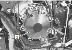
- Remove the gasket (3) and dowel pins.
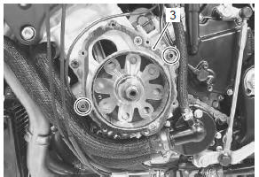
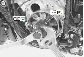
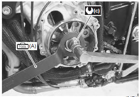
- Hold the generator rotor with the special tool and remove the generator rotor bolt.
Special tool
 (a): 09930–44530 (rotor holder)
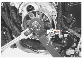
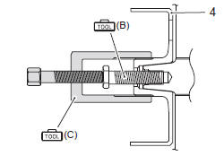
- Screw in the special tool to the crankshaft.
- Remove the generator rotor (4) using the special tool.
Special tool
 (b): 09930–30460 (rotor remover
bolt)
 (c): 09930–34970 (rotor remover)
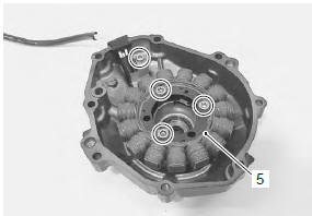
- Remove the generator stator (5).
Installation
Install the generator in the reverse order of removal. Pay attention to the following points:
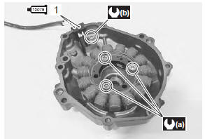
- tighten the generator stator set bolts and generator lead wire set bolt to the specified torque.
Tightening torque generator stator set bolt (a): 11 n·m (1.1 Kgf-m, 8.0 Lbf-ft) generator lead wire set bolt (b): 5.5 N·m (0.55 Kgfm, 4.0 Lbf-ft)
- Apply bond lightly to the generator lead wire grommet (1).
 : Sealant 99000–31140 (suzuki
bond
no.1207B or equivalent)
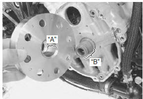
- Degrease the tapered portion “a” of generator rotor and also the crankshaft “b” with nonflammable cleaning solvent.
| Caution dry these parts naturally. Do not wipe them with a cloth or use compressed air to dry. |
- Install the generator rotor onto crankshaft.
- Hold the generator rotor with the special tool and tighten its bolt to the specified torque.
Special tool
 (a): 09930–44530 (rotor holder)
Tightening torque generator rotor bolt (c): 145 n·m (14.5 Kgf-m, 105.0 Lbf-ft)
- Apply a bond lightly to the mating surfaces at the parting line between the upper and lower crankcases as shown.
 : Sealant 99000–31140 (suzuki
bond
no.1207B or equivalent)
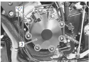
- Install the dowel pins and new gasket (2).
| Caution use new gasket to prevent oil leakage. |
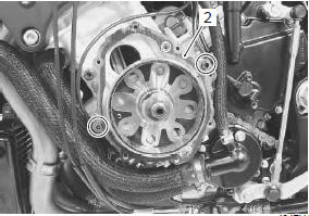
- Install the generator cover (3) and tighten the generator cover bolts.
 Be careful Be careful
not to pinch the finger between the generator cover and crankcase. |
| Note fit the clamp to the generator cover bolt “c”. |
- Route the generator lead wire. Refer to “wiring harness routing diagram” in section 9a .
 Generator inspection
Generator coil resistance
Remove the left side cowling. Refer to “exterior parts removal and
installation” in section 9d .
Disconnect the generator coupler (1).
Measure the re ...
 Regulator / rectifier construction
Regulator/rectifier
Regulator/rectifier bracket
Air intake pipe (rh)
Spacer
Wiring harness
Connect
the regulator/rectifier couplers under the wiring harnes ...
Other materials:
Vehicle side view
Note
difference between illustrations and actual
motorcycles may exist depending on the
markets.
Suzuki gsx-r1000 (2009-model)
Right side
Left side ...
Battery removal and installation
Removal
Remove the front seat. Refer to “exterior parts
removal and installation” in section 9d (page 9d-
6).
Disconnect the battery (–) lead wire (1).
Disconnect the battery (+) lead wire (2).
Note
be sure to disconnect the battery (–) lead
wire (1) first, th ...
Exhaust pipe bolt and muffler bolt inspection
Tighten exhaust pipe bolts and muffler bolts
initially at 1 000 km (600 miles, 2 months) and every
12 000 km (7 500 miles, 24 months) thereafter
Check the exhaust pipe bolts and muffler bolts to the
specified torque.
Tightening torque
exhaust pipe bolt (a): 23 n·m (2.3 Kgf-m, 16.5 Lbf-ft)
muf ...