Suzuki GSX-R 1000 Service Manual: Cylinder head related parts inspection
Refer to “cylinder head disassembly and assembly” .
Cylinder head distortion
- Decarbonize the combustion chambers.
- Check the gasket surface of the cylinder head for
distortion. Use a straightedge and thickness gauge.
Take clearance readings at several places. If readings exceed the service limit, replace the cylinder head.
Special tool
 : 09900–20803 (thickness gauge)
Cylinder head distortion service limit: 0.02 Mm (0.0008 In)
Valve stem runout
Support the valve using v-blocks, as shown in the figure, and check its runout using the dial gauge. If the runout exceeds the service limit, replace the valve.
Special tool
 (a): 09900–20607 (dial gauge)
 (b): 09900–20701 (dial gauge chuck)
 (c): 09900–21304 (v blocks)
Valve stem runout (in. & Ex.) Service limit: 0.05 Mm (0.002 In)
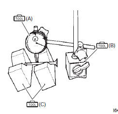
Valve head radial runout
Place the dial gauge at a right angle to the valve head face and measure the valve head radial runout. If it measures more than the service limit, replace the valve.
Special tool
 (a): 09900–20607 (dial gauge)
 (b): 09900–20701 (dial gauge chuck)
 (c): 09900–21304 (v blocks)
Valve head radial runout (in. & Ex.) Service limit: 0.03 Mm (0.001 In)
Valve stem and valve face wear condition
Visually inspect each valve stem and valve face for wear and pitting. If it is worn or damaged, replace the valve with a new one.
Valve stem deflection
Lift the valve about 10 mm (0.39 In) from the valve seat.
Measure the valve stem deflection in two directions, “x” and “y”, perpendicular to each other. Position the dial gauge as shown. If the deflection exceeds the service limit, then determine whether the valve or the guide should be replaced with a new one.
Special tool
 (a): 09900–20607 (dial gauge)
 (b): 09900–20701 (dial gauge chuck)
Valve stem deflection (in. & Ex.) Service limit: 0.25 Mm (0.010 In)
Valve stem wear
Measure the valve stem o.D. Using the micrometer. If it is out of specification, replace the valve with a new one.
If the valve stem o.D. Is within specification but the valve stem deflection is not, replace the valve guide. After replacing the valve or valve guide, recheck the deflection.
Special tool
 (a): 09900–20205 (micrometer (0 – 25
mm))
Valve stem o.D.
Standard (in.): 4.475 – 4.490 Mm (0.1762 – 0.1768 In) standard (ex.): 4.455 – 4.470 Mm (0.1754 – 0.1760 In)
| Note if valve guides have to be removed for replacement after inspecting related parts, carry out the steps shown in valve guide replacement. Refer to “valve guide replacement” . |
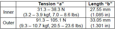
Valve spring
The force of the coil springs keep the valve seat tight. A weakened spring results in reduced engine power output and often accounts for the chattering noise coming from the valve mechanism.
Check the valve springs for proper strength by measuring their free length and also by the force required to compress them. If the spring length is less than the service limit or if the force required to compress the spring does not fall within the specified range, replace both the inner and outer springs as a set.
Special tool
 (a): 09900–20102 (vernier calipers
(200 mm))
Valve spring free length (in. & Ex.) Service limit: inner: 30.1 Mm (1.19 In) service limit: outer: 35.3 Mm (1.39 In)
Valve spring tension (in. & Ex.) Standard: inner: 31.3 – 38.3 N (3.2 – 3.9 Kgf, 7.0 – 8.6 Lbs)/27.55 Mm (1.085 In) standard: outer: 91.3 – 105.1 N (9.3 – 10.7 Kgf, 20.5 – 23.6 Lbs)/33.05 Mm (1.301 In)
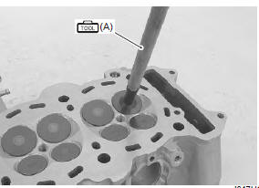
Valve seat width
- Visually check for valve seat width on each valve face. If the valve face has worn abnormally, replace the valve.
- Coat the valve seat with a red lead (prussian blue) and set the valve in place.
| Caution do not use lapping compound. |
- Rotate the valve with light pressure.
Special tool
 (a): 09916–10911 (valve lapper set)
- Check that the transferred red lead (blue) on the
valve face is uniform all around and in center of the
valve face.
If the seat width “a” measured exceeds the standard value, or seat width is not uniform reface the seat using the seat cutter. Refer to “valve seat repair” .
Valve seat width “a” (in. & Ex.) Standard: 0.9 – 1.1 Mm (0.035 – 0.043 In)
Valve seat sealing condition
- Clean and assemble the cylinder head and valve components.
- Fill the intake and exhaust ports with gasoline to check for leaks. If any leaks occur, inspect the valve seat and face for burrs or other things that could prevent the valve from sealing. Refer to “valve seat repair” .
 Always use Always use
extreme caution when handling gasoline. |
| Note after servicing the valve seats, be sure to check the valve clearance after the cylinder head has been reinstalled. Refer to “valve clearance inspection and adjustment” in section 0b . |
 Cylinder head disassembly and assembly
Refer to “engine top side disassembly” .
Refer to “engine top side assembly” .
Caution
identify the position of each removed part.
Organize the parts in their respective groups
(i. ...
 Valve guide replacement
Remove the cylinder head. Refer to “engine top side disassembly” .
Remove the valves. Refer to “cylinder head disassembly and assembly” .
Using the valve guide remover, drive the va ...
Other materials:
Light bulb replacement
The wattage rating of each bulb is
shown in the following chart.
When replacing a burned-out
bulb, always use the same wattage
rating according to the following
chart.
Caution
Using a light bulb with the
wrong wattage rating can
cause electrical system damage
or shorte ...
Crankcase emission control system
description
The engine is equipped with a pcv system to prevent discharging crankcase
emissions into the atmosphere. Blow-by
gas in the engine is constantly drawn into the crankcase, which is returned to
the combustion chamber through the
pcv (breather) hose, air cleaner and throttle body.
...
Dimmer / passing light switch inspection
Inspect the dimmer/passing light switch in the following
procedures:
remove the air cleaner box. Refer to “air cleaner box removal and
installation” in section 1d .
Disconnect the left handlebar switch coupler (1).
(Yellow)
Inspect the dimmer/passing light switch ...