Suzuki GSX-R 1000 Service Manual: Valve guide replacement
- Remove the cylinder head. Refer to “engine top side disassembly” .
- Remove the valves. Refer to “cylinder head disassembly and assembly” .
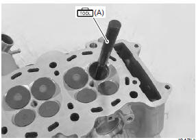
- Using the valve guide remover, drive the valve guide out toward the intake or exhaust camshaft side.
Special tool
 (a): 09916–43211 (valve guide
installer &
remover)
Note
|
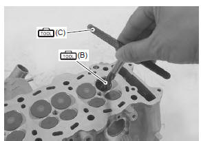
- Refinish the valve guide holes in the cylinder head using the reamer and handle.
| Caution when refinishing or removing the reamer from the valve guide hole, always turn it clockwise. |
Special tool
 (b): 09916–33320 (valve guide reamer
(9.8
Mm))
 (c): 09916–34542 (reamer handle)
- Cool down the new valve guides in a freezer for about one hour and heat the cylinder head to 100 – 150 °c (212 – 302 °f) with a hot plate.
| Caution do not use a burner to heat the valve guide hole to prevent cylinder head distortion. |
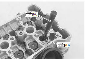
- Apply engine oil to each valve guide and valve guide hole.
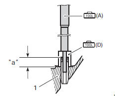
- Drive the guide into the guide hole using the valve guide installer.
| Caution failure to oil the valve guide hole before driving the new guide into place may result in a damaged guide or head. |
Special tool
(a): 09916–43211 (valve guide
installer &
remover)
(d): 09916–53380 (valve guide
installer
attachment)
|
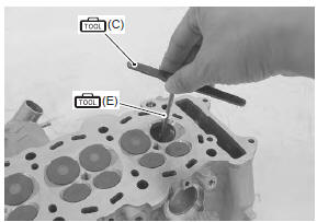
- After installing the valve guides, refinish their guiding bores using the reamer. Be sure to clean and oil the guides after reaming.
Note
|
Special tool
(c): 09916–34542 (reamer handle)
(e): 09916–33210 (valve guide reamer
(4.5
Mm))
- Reassemble the cylinder head. Refer to “cylinder head disassembly and assembly” .
- Install the cylinder head assembly. Refer to “engine top side assembly” .
 Cylinder head related parts inspection
Refer to “cylinder head disassembly and assembly” .
Cylinder head distortion
Decarbonize the combustion chambers.
Check the gasket surface of the cylinder head for
distortion. Use a str ...
 Valve seat repair
The valve seats (1) for both the intake and exhaust
valves are machined to three different angles. The seat
contact surface is cut at 45°.
Intake valve
Exhaust valve
...
Other materials:
Specifications
Tightening torque specifications
Note
the specified tightening torque is described in the following.
“Handlebar components” “steering components” “steering
damper construction”
Reference: for the tightening torque of fastener not specified in this
section ...
Cooling fan relay inspection
Inspect the fan relay in the following procedures:
remove the frame covers. Refer to “exterior parts
removal and installation” in section 9d (page 9d-
6).
Remove the cooling fan relay (1).
First check the insulation between “a” and “b”
terminals with tester. Then ap ...
Washing the motorcycle
When washing the motorcycle,
follow the instructions below:
Remove dirt and mud from the
motorcycle with running water.
You may use a soft sponge or
brush. Do not use hard materials
which can scratch the
paint.
Wash the entire motorcycle
with a mild detergent or car
...