Suzuki GSX-R 1000 Service Manual: DTC “c21” (p0110-h/l): iat sensor circuit malfunction
Detected condition and possible cause
|
Detected condition |
Possible cause |
||
| C21 | Output voltage is not with in the following
range.
0.15 V ≤ Sensor voltage < 4.85 V |
|
|
| P0110 | H | Sensor voltage is higher than specified value. | |
| L | Sensor voltage is lower than specified value. | ||
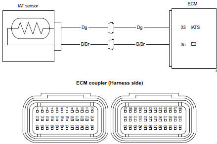
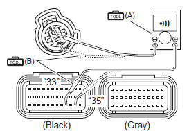
Wiring diagram
Troubleshooting
| Caution when using the multi-circuit tester, do not strongly touch the terminal of the ecm coupler with a needle pointed tester probe to prevent terminal damage. |
| Note after repairing the trouble, clear the dtc using sds tool. Refer to “use of sds diagnosis reset procedures” . |
C21 (use of mode select switch)
|
Step |
Action |
Yes |
No |
|
1 |
Special tool Tester knob indication
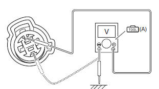
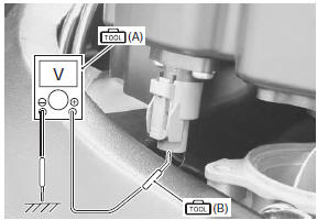
voltage ( Iat sensor input voltage 4.5 – 5.5 V ((+) terminal: dg – (–) terminal: ground, (+) terminal: dg – (–) terminal: b/br)
Is the voltage ok? |
Go to step 2. |
|
 (a): 09900–25008 (multi
 )
)
P0110-h (use of sds)
|
Step |
Action |
Yes |
No |
|
1 |
Special tool Tester knob indication
continuity test ( Ecm couplers (harness side)
Is the continuity ok? |
Connect the ecm coupler and go to step 2. | Dg or b/br wire open. |
 (a): 09900–25008 (multi
 (b): 09900–25009
 )
)
P0110-l (use of sds)
|
Step |
Action |
Yes |
No |
|
|
1 |
Special tool Tester knob indication
continuity test (
Special tool Tester knob indication
voltage ( Iat sensor output voltage 0.15 – 4.85 V ((+) terminal: dg – (–) terminal: ground)
Are the continuity and voltage ok? |
Go to step 2. |
|
|
|
2 |
Special tool Tester knob indication resistance (Ω) Iat sensor resistance approx. 2.58 KΩ at 20 °c (68 °f) (terminal – terminal)
Is the resistance ok? |
|
Replace the iat sensor with a new one. Refer to “iat sensor removal and installation” in section 1c (page 1c- 5). |
 (a): 09900–25008 (multi
 )
)
 )
)
 DTC “c15” (p0115-h/l): ect sensor circuit
malfunction
DTC “c15” (p0115-h/l): ect sensor circuit
malfunction
Detected condition and possible cause
Detected condition
Possible cause
C15
Output voltage is not with in the following
range.
0.15 V ≤ Sensor voltage < ...
 DTC “c22” (p1450-h/l): ap sensor circuit
malfunction
DTC “c22” (p1450-h/l): ap sensor circuit
malfunction
Detected condition and possible cause
Detected condition
Possible cause
C22
Ap sensor voltage is not within the
following range.
0.5 V ≤ Sensor voltage < ...
Other materials:
Fuel injector inspection and cleaning
Inspect the fuel injector in the following procedures:
remove the fuel injector. Refer to “throttle body disassembly and
assembly” in section 1d .
Check the fuel injector for evidence of dirt and
contamination. If present, clean and check for
presence of dirt in the fuel lin ...
Specifications
Service data
Electrical
unit: mm (in)
Tightening torque specifications
Reference: for the tightening torque of fastener not specified in this
section, refer to “tightening torque list” in section 0c . ...
Ect sensor removal and installation
Removal
Remove the left side cowling. Refer to “exterior parts removal and
installation” in section 9d .
Drain engine coolant. Refer to “cooling system inspection” in section
0b .
Disconnect the coupler and remove the ect sensor
(1).
Caution
take special care ...