Suzuki GSX-R 1000 Service Manual: DTC “c22” (p1450-h/l): ap sensor circuit malfunction
Detected condition and possible cause
|
Detected condition |
Possible cause |
|||
| C22 | Ap sensor voltage is not within the
following range.
0.5 V ≤ Sensor voltage < 4.85 V
|
|
||
| P1450 | H | Sensor voltage is higher than specified value. | ||
|
L |
Sensor voltage is lower than specified value. | |||
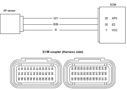
Wiring diagram
Troubleshooting
| Caution when using the multi-circuit tester, do not strongly touch the terminal of the ecm coupler with a needle pointed tester probe to prevent terminal damage. |
| Note after repairing the trouble, clear the dtc using sds tool. Refer to “use of sds diagnosis reset procedures” . |
C22 (use of mode select switch)
|
Step |
Action |
Yes |
No |
|
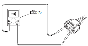
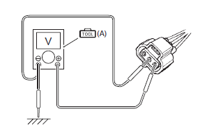
1 |
Special tool Tester knob indication
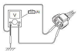
voltage ( Ap sensor input voltage 4.5 – 5.5 V ((+) terminal: r – (–) terminal: ground, (+) terminal: r – (–) terminal: b/br)
Is the voltage ok? |
Go to step 3. |
|
 (a): 09900–25008 (multi
 )
)
P1450-h (use of sds)
|
Step |
Action |
Yes |
No |
|
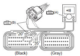
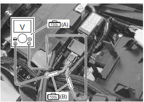
1 |
Special tool Tester knob indication
continuity (
Special tool Tester knob indication
continuity test ( Ecm coupler (harness side)
Is the continuity ok? |
Go to step 3. | G/y wire shorted to vcc, or b/br wire open. |
 (a): 09900–25008 (multi
 )
)
 )
)
P1450-l (use of sds)
|
Step |
Action |
Yes |
No |
|
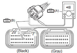
1 |
Special tool Tester knob indication
continuity (
Special tool Tester knob indication
continuity ( Ecm coupler (harness side)
Is the continuity ok? |
Go to step 2. | R and g/y wire open, g/ y wire shorted to ground. |
|
2 |
Special tool
Tester knob indication
voltage ( Ap sensor input voltage 4.5 – 5.5 V ((+) terminal: r – (–) terminal: ground, (+) terminal: r – (–) terminal: b/br)
Is the voltage ok? |
Go to step 3. |
|
|
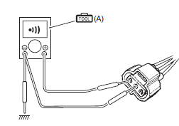
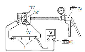
3 |
Special tool Tester knob indication
voltage ( Ap sensor output voltage approx. 3.6 V at 100 kpa (760 mmhg) ((+) terminal: g/y – (–) terminal: b/br)
Is the voltage ok? |
Go to step 4. |
|
|
4 |
Special tool Tester knob indication
voltage (
Is the voltage ok? |
|
If check result is not satisfactory, replace the ap sensor with a new one. Refer to “ap sensor removal and installation” in section 1c . |
 (a): 09900–25008 (multi
 )
)
 )
)
 DTC “c21” (p0110-h/l): iat sensor circuit
malfunction
DTC “c21” (p0110-h/l): iat sensor circuit
malfunction
Detected condition and possible cause
Detected condition
Possible cause
C21
Output voltage is not with in the following
range.
0.15 V ≤ Sensor voltage < ...
 DTC “c23” (p1651-h/l): to sensor circuit
malfunction
DTC “c23” (p1651-h/l): to sensor circuit
malfunction
Detected condition and possible cause
Detected condition
Possible cause
C23
The sensor voltage should be the
following for 2 sec. And more, after ignition
switch i ...
Other materials:
Rear wheel components
Rear axel nut
Collar
Dust seal
Bearing
Retainer
Rear sprocket
Sprocket mounting drum
Wheel damper
Bearing
Spacer
Air valve
Rear wheel
Wheel balancer
Rear tire
Dust seal
Collar
Rear brake disc
Rear axle
1 ...
Front brake hose removal and installation
Removal
Drain brake fluid. Refer to “brake fluid replacement” .
2) Remove the front brake hoses as shown in the front brake hose routing
diagram. Refer to “front brake hose routing diagram” .
Installation
Caution
the seal washers should be replaced with the
new ones to pr ...
Ap sensor removal and installation
Removal
Remove the front seat. Refer to “exterior parts
removal and installation” in section 9d (page 9d-
6).
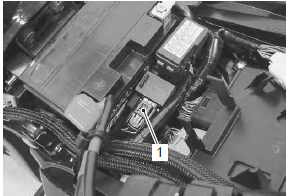
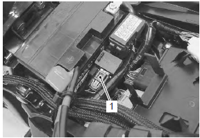
Disconnect the starter relay (1) from the holder.
Disconnect the coupler (2) and remove the ap
sensor (3).
Installation
Install the ap sensor in the rever ...