Suzuki GSX-R 1000 Service Manual: DTC “c23” (p1651-h/l): to sensor circuit malfunction
Detected condition and possible cause
|
Detected condition |
Possible cause |
||
| C23 | The sensor voltage should be the
following for 2 sec. And more, after ignition
switch is turned on.
0.2 V ≤ Sensor voltage < 4.8 V |
|
|
| P1651 | H | Sensor voltage is higher than specified value. | |
| L | Sensor voltage is lower than specified value. | ||
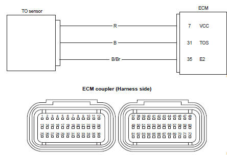
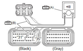
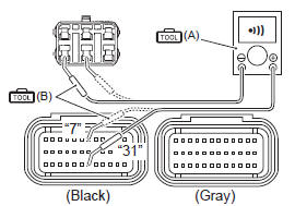
Wiring diagram
Troubleshooting
| Caution when using the multi-circuit tester, do not strongly touch the terminal of the ecm coupler with a needle pointed tester probe to prevent terminal damage. |
| Note after repairing the trouble, clear the dtc using sds tool. Refer to “use of sds diagnosis reset procedures” . |
C23 (use of mode select switch)
|
Step |
Action |
Yes |
No |
|
1 |
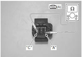
Special tool Tester knob indication resistance (Ω) To sensor resistance 16.5 – 22.3 KΩ (terminal “a” – terminal “c”)
Is the resistance ok? |
Go to step 2. | Replace the to sensor with a new one. Refer to “to sensor removal and installation” in section 1c (page 1c- 6). |
 (a): 09900–25008 (multi
P1651-h (use of sds)
|
Step |
Action |
Yes |
No |
|
1 |
Special tool Tester knob indication
continuity test (
Special tool Tester knob indication
continuity test ( Ecm coupler (harness side)
Is the continuity ok? |
Go to step 2. | B wire shorted to vcc, or b/br wire open. |
 (a): 09900–25008 (multi
 )
)
 )
)
P1651-l (use of sds)
|
Step |
Action |
Yes |
No |
|
1 |
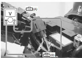
Special tool Tester knob indication continuity test (
Special tool Tester knob indication continuity test (
) Ecm coupler (harness side)
Is the continuity ok? |
Go to step 2. | R or b wire open, or b wire shorted to ground. |
|
2 |
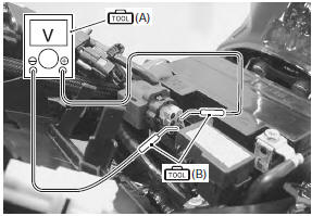
Special tool Tester knob indication
voltage ( To sensor voltage (normal) 0.4 – 1.4 V ((+) terminal: b – (–) terminal: b/br)
Special tool To sensor voltage (leaning) 3.7 – 4.4 V ((+) terminal: b – (–) terminal: b/br)
Is the voltage ok? |
|
|
 )
)
DTC “c24” (p0351), “c25” (p0352), “c26” (p0353) or “c27” (p0354): ignition system malfunction
| Note refer to “no spark or poor spark” in section 1h for details. |
 DTC “c22” (p1450-h/l): ap sensor circuit
malfunction
DTC “c22” (p1450-h/l): ap sensor circuit
malfunction
Detected condition and possible cause
Detected condition
Possible cause
C22
Ap sensor voltage is not within the
following range.
0.5 V ≤ Sensor voltage < ...
 DTC “c28” (p1655): secondary throttle
valve actuator (stva) malfunction
DTC “c28” (p1655): secondary throttle
valve actuator (stva) malfunction
Detected condition and possible cause
Detected condition
Possible cause
The operation voltage does not reach the stva.
Ecm does not receive communication signal from the ...
Other materials:
Front brake pad replacement
Loosen the pad mounting pins (1).
Remove the brake caliper by removing the caliper
mounting bolts (2).
Remove the pad mounting pins (1), brake pads and
spring.
Caution
do not operate the brake lever while the pads
are removed.
Note
when ...
Rear brake master cylinder components
Reservoir cap
Plate
Diaphragm
Reservoir tank
Reservoir hose
Brake hose
Brake hose union bolt
Brake hose connector
Master cylinder
Spring
Piston/cup set
Push rod
Dust boot
23 N·m (2.3 Kgf-m,
16.5 Lbf-ft)
10 N·m
...
Rear wheel dust seal / bearing removal and installation
Removal
Remove the rear wheel assembly. Refer to “rear wheel assembly removal
and installation” .
Remove the rear sprocket mounting drum assembly
(1) from the rear wheel.
Remove the wheel dampers (2).
Remove the dust seal.
Special tool
(a): 09913–50121 (oil s ...