Suzuki GSX-R 1000 Service Manual: Throttle body construction
|
 Face
Face
 Yellow
 Face the
 Arrange the
 Yellow
 Face the
 Face the
 Tighten the
 Route the
 Pass the
 Face the
 8.5
8.5
 1.5 N·m
 7 N·m (0.7
 10 N·m (1.0
 1.3 N·m
 4.3 N·m
 25 N·m (2.5
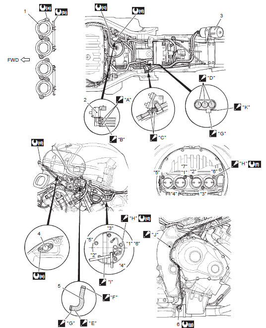
 Throttle body components
Fuel delivery pipe
Fuel delivery pipe t-joint
O-ring
Tp sensor
Stp sensor
Secondary fuel injector
Primary fuel injector
Cushion seal
Isc valve
A ...
 Throttle body removal and installation
Removal
Remove the side cowlings. Refer to “exterior parts
removal and installation” in section 9d (page 9d-
6).
Remove the air cleaner box. Refer to “air cleaner box removal and
in ...
Other materials:
Rear brake light switch inspection
Inspect the rear brake light switch in the following
procedures:
lift and support the fuel tank. Refer to “fuel tank
removal and installation” in section 1g (page 1g-
9).
Disconnect the rear brake light switch lead wire
coupler (1).
Inspect the rear brake light swi ...
Starter torque limiter removal and
installation
Removal
Remove the clutch assembly. Refer to “clutch removal” in section 5c .
Remove the washer (1), starter idle gear no. 1 (2)
And starter torque limiter (3).
Installation
Installation is in the reverse order of removal. Pay
attention to the following point:
apply ...
Piston ring removal and installation
Removal
Remove the piston. Refer to “engine bottom side disassembly” .
Carefully spread the ring opening with your thumbs
and then push up the opposite side of the 1st ring to
remove it.
Note
do not expand the piston ring excessively
since it is apt to be broken down. ...