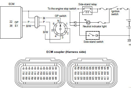
Suzuki GSX-R 1000 Service Manual: DTC “c31” (p0705): gp switch circuit malfunction
Detected condition and possible cause
|
Detected condition |
Possible cause |
| No gear position switch voltage
Gp switch voltage is not within the following range. Gp switch voltage > 0.6 V |
|
Wiring diagram
Troubleshooting
| Caution when using the multi-circuit tester, do not strongly touch the terminal of the ecm coupler with a needle pointed tester probe to prevent terminal damage. |
| Note after repairing the trouble, clear the dtc using sds tool. Refer to “use of sds diagnosis reset procedures” . |
|
Step |
Action |
Yes |
No |
|
1 |
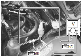
Special tool Tester knob indication voltage ( ) Gp switch voltage 0.6 V and more ((+) terminal: p – (–) terminal: b/w)
Is the voltage ok? |
|
|
 DTC “c29” (p1654-h/l): secondary throttle
position sensor (stps) circuit malfunction
DTC “c29” (p1654-h/l): secondary throttle
position sensor (stps) circuit malfunction
Detected condition and possible cause
Detected condition
Possible cause
C29
Output voltage is not within the following
range.
Difference between actual throttle op ...
 Dtc “c32” (p0201), “c33” (p0202), “c34” (p0203) or “c35” (p0204): primary
fuel injector circuit
malfunction
Dtc “c32” (p0201), “c33” (p0202), “c34” (p0203) or “c35” (p0204): primary
fuel injector circuit
malfunction
Detected condition and possible cause
Detected condition
Possible cause
Ckp signal is produced but fuel injector signal is
interrupted by 4 times or more continuity
...
Other materials:
Water pump components
Impeller
Mechanical seal
Oil seal
O-ring
O-ring
8
N·m (0.8 Kgf-n, 6.0 Ib-ft)
10 N·m
(1.0 Kgf-n, 7.0 Ib-ft)
6 N·m (0.6
Kgf-n, 4.5 Ib-ft)
13 N·m
(1.3 Kgf-n, 9.5 Ib-ft)
Apply grease.
Apply engine coolant.
Apply molyb ...
Throttle body removal and installation
Removal
Remove the side cowlings. Refer to “exterior parts
removal and installation” in section 9d (page 9d-
6).
Remove the air cleaner box. Refer to “air cleaner box removal and
installation” .
Remove the clamps (1).
Disconnect the iap sensor (2) from the vacuum
...
Inspection before riding
Warning
Failure to inspect and maintain
your motorcycle properly
increases the chance of an
accident or equipment damage.
Always perform a pre-ride
inspection before each ride.
Refer to the table on page 4-4
for check items. For further
details, refer to the inspec· ...