Suzuki GSX-R 1000 Service Manual: Dtc “c32” (p0201), “c33” (p0202), “c34” (p0203) or “c35” (p0204): primary fuel injector circuit malfunction
Detected condition and possible cause
|
Detected condition |
Possible cause |
| Ckp signal is produced but fuel injector signal is interrupted by 4 times or more continuity |
|
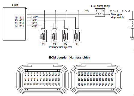
Wiring diagram
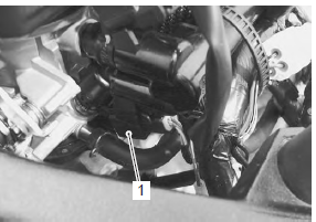
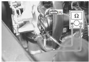
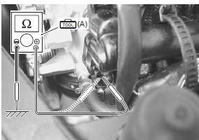
Troubleshooting
| Caution when using the multi-circuit tester, do not strongly touch the terminal of the ecm coupler with a needle pointed tester probe to prevent terminal damage. |
| Note after repairing the trouble, clear the dtc using sds tool. Refer to “use of sds diagnosis reset procedures” . |
|
Step |
Action |
Yes |
No |
|
|
1 |
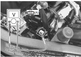
Special tool Tester knob indication resistance (Ω) Injector resistance 11 – 13 Ω at 20 °c (68 °f) (terminal – terminal)
Special tool Injector continuity ∞Ω¶ (infinity)
Are the resistance and continuity ok? |
Go to step 2. | Replace the injector with a new one. Refer to “throttle body disassembly and assembly” in section 1d . | |
|
2 |
Special tool Tester knob indication
voltage ( Injector voltage battery voltage ((+) terminal: y/r – (–) terminal: ground)
Is the voltage ok? |
|
Open circuit in the y/r wire. |
 (a): 09900–25008 (multi
 )
)
 DTC “c31” (p0705): gp switch circuit
malfunction
DTC “c31” (p0705): gp switch circuit
malfunction
Detected condition and possible cause
Detected condition
Possible cause
No gear position switch voltage
Gp switch voltage is not within the following range.
Gp switch ...
 Dtc “c36” (p1764), “c37” (p1765), “c38” (p1766) or “c39” (p1767): secondary
fuel injector circuit
malfunction
Dtc “c36” (p1764), “c37” (p1765), “c38” (p1766) or “c39” (p1767): secondary
fuel injector circuit
malfunction
Detected condition and possible cause
Detected condition
Possible cause
Some failure exists in the fuel injector signal in a high
load, high revolution condition.
...
Other materials:
Oil cooler / oil cooler hose removal and
installation
Refer to “electrical components location” in section 0a .
Removal
Turn the ignition switch off.
Remove the left side cowling. Refer to “exterior parts removal and
installation” in section 9d .
Drain engine oil. Refer to “engine oil and filter replacement” in
section 0b .
...
DTC “c44” (p0130/p0135): ho2 sensor
(ho2s) circuit malfunction
Detected condition and possible cause
Detected condition
Possible cause
C44/P0130
Ho2 sensor output voltage is not input to
ecm during engine operation and running
condition.
Sensor voltage > 1.0 V
Ho2 sensor circuit is open or shorted to the po ...
Specifications
Service data
Oil pump
Oil
Tightening torque specifications
Reference: for the tightening torque of fastener not specified in this
section, refer to “tightening torque list” in section 0c . ...