
Suzuki GSX-R 1000 Service Manual: Oil cooler / oil cooler hose removal and installation
Refer to “electrical components location” in section 0a .
Removal
- Turn the ignition switch off.
- Remove the left side cowling. Refer to “exterior parts removal and installation” in section 9d .
- Drain engine oil. Refer to “engine oil and filter replacement” in section 0b .
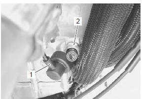
- Disconnect the oil pressure switch lead wire (1).
- Remove the oil pressure switch (2).
Installation
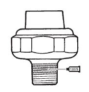
- Apply bond to the thread part of oil pressure switch and tighten oil pressure switch to the specified torque.
| Note be careful not to apply bond to the hole of thread end. |
: Sealant 99000–31140 (suzuki bond no.1207B or equivalent)
Tightening torque oil pressure switch: 14 n·m (1.4 Kgf-m, 10.0 Lbfft)
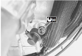
- Route the oil pressure switch lead wire properly and tighten the screw to the specified torque. Refer to “wiring harness routing diagram” in section 9a .
Tightening torque oil pressure switch lead wire screw (a): 1.5 N·m (0.15 Kgf-m, 1.1 Lbf-ft)
- Pour engine oil. Refer to “engine oil and filter replacement” in section 0b .
- Install the removed parts.
Oil pressure switch inspection
Refer to “oil pressure indicator inspection” in section 9c .
 Oil cooler / oil cooler hose inspection and
cleaning
Oil cooler / oil cooler hose inspection and
cleaning
Refer to “exterior parts removal and installation” in section 9d .
Oil cooler hose inspection
Inspect the oil cooler hoses for any damage and oil
leakage. If any defects are found, replace the oil ...
 Oil jet removal and installation
Piston cooling oil jet
Removal
Remove the engine assembly. Refer to “engine assembly removal” in
section 1d .
Remove the crankshaft assembly. Refer to “engine
bottom side disassembly ...
Other materials:
Turn signal light
To replace the turn signal light
bulb, follow these directions.
Remove screw and take off
the lens.
Turn the socket counterclockwise
and remove it.
Push in the bulb and turn it
counterclockwise.
Caution
Overtightening the screws may
cause the le ...
Clutch components
Clutch pressure plate
Clutch push piece
No. 1 Drive plate (8 pcs.)
No. 3 Driven plate (0 – 2 pcs.)
No. 1 Driven plate (5 – 7 pcs.)
No. 2 Driven plate (1 pc.)
No. 2 Drive plate (1 pc.)
Spring washer
Spring washer seat
Clutch sleeve hub
Seat ...
Evaporative emission control system
diagram (only for e-33)
Fuel tank
Fuel-vapor separator
Fuel pump
Fuel feed hose
Fuel shut-off valve
Iap sensor
Surge hose
Evap canister
Purge hose
Evap system purge control solenoid valve
Fue
Hc vapor
Fresh air
Vacuum
...