Suzuki GSX-R 1000 Service Manual: Oil jet removal and installation
Piston cooling oil jet
Removal
- Remove the engine assembly. Refer to “engine assembly removal” in section 1d .
- Remove the crankshaft assembly. Refer to “engine bottom side disassembly” in section 1d (page 1d- 49).
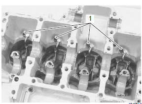
- Remove the piston cooling oil jets (1) from the upper crankcase.
Installation
Installation is in the reverse order of removal. Pay attention to the following points:
- fit new o-ring (1) to each piston cooling oil jet and apply engine oil to it.
| Caution use new o-rings to prevent oil pressure leakage. |
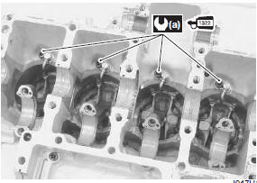
- Apply a small quantity of thread lock to the bolts and tighten them to the specified torque.
 : Thread lock cement
99000–32110
(thread lock cement super “1322” or
equivalent)
Tightening torque piston cooling oil jet bolt (a): 10 n·m (1.0 Kgf-m, 7.0 Lbf-ft)
Oil jet (for cam chain tension adjuster)
Removal
- Remove the throttle body. Refer to “throttle body removal and installation” in section 1d (page 1d- 10).
- Remove the regulator/rectifier. Refer to “regulator / rectifier removal and installation” in section 1j .
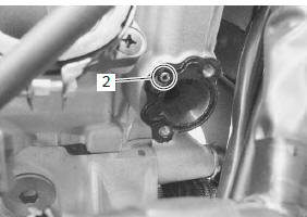
- Remove the cam chain tension adjuster (1). Refer to “engine top side disassembly” in section 1d .
- Remove the oil jet (2) (for cam chain tension adjuster).
Installation
Installation is in the reverse order of removal. Pay attention to the following points:
- apply engine oil to the o-ring.
| Caution use a new o-ring to prevent oil leakage. |
- Install the cam chain tension adjuster. Refer to “engine top side assembly” in section 1d (page 1d- 28).
- Install the regulator/rectifier. Refer to “regulator / rectifier removal and installation” in section 1j .
- Install the throttle body. Refer to “throttle body removal and installation” in section 1d (page 1d- 10).
Oil jet (for transmission)
Removal
- Remove the engine assembly. Refer to “engine assembly removal” in section 1d .
- Separate the crankcases, upper and lower. Refer to “engine bottom side disassembly” in section 1d .
- Remove the oil jet (1) (for transmission) from the lower crankcase.
Installation
Installation is in the reverse order of removal. Refer to “engine bottom side assembly” in section 1d .
 Oil cooler / oil cooler hose removal and
installation
Oil cooler / oil cooler hose removal and
installation
Refer to “electrical components location” in section 0a .
Removal
Turn the ignition switch off.
Remove the left side cowling. Refer to “exterior parts removal and
installation” in sect ...
 Oil jet inspection
Refer to “oil jet removal and installation” .
Oil jet
Make sure that the oil jets are not clogged. If they are
clogged, clean their oil passage using a wire of the
proper size and compressed air.
...
Other materials:
Front brake master cylinder / brake lever disassembly and assembly
Refer to “front brake master cylinder assembly removal and installation” .
Disassembly
Remove the reservoir cap (1), plate (2), diaphragm
(3) and reservoir tank (4).
Remove the brake light switch (5) and brake lever
(6).
Remove the dust boot (7) and push rod (8).
...
Rear brake master cylinder components
Reservoir cap
Plate
Diaphragm
Reservoir tank
Reservoir hose
Brake hose
Brake hose union bolt
Brake hose connector
Master cylinder
Spring
Piston/cup set
Push rod
Dust boot
23 N·m (2.3 Kgf-m,
16.5 Lbf-ft)
10 N·m
...
Accessory installation
guideline
Install aerodynamic affecting
accessories, such as a fairing,
windshield, backrests, saddlebags,
and travel trunks, as low
as possible, as close to the
motorcycle and as near the
center of gravity as is feasible.
Check that the mounting
brackets and other attachment
hardware are ...