Suzuki GSX-R 1000 Service Manual: Dtc “c36” (p1764), “c37” (p1765), “c38” (p1766) or “c39” (p1767): secondary fuel injector circuit malfunction
Detected condition and possible cause
|
Detected condition |
Possible cause |
| Some failure exists in the fuel injector signal in a high load, high revolution condition. |
|
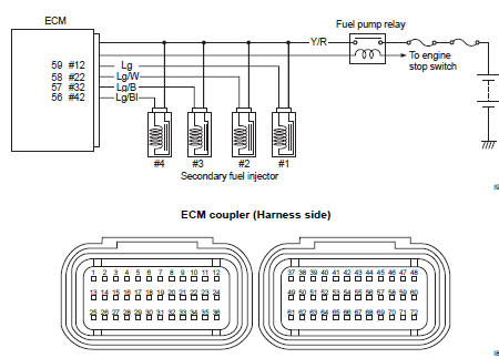
Wiring diagram
Troubleshooting
| Caution when using the multi-circuit tester, do not strongly touch the terminal of the ecm coupler with a needle pointed tester probe to prevent terminal damage. |
| Note after repairing the trouble, clear the dtc using sds tool. Refer to “use of sds diagnosis reset procedures” . |
|
Step |
Action |
Yes |
No |
|
|
1 |
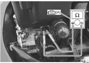
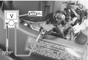
Special tool Tester knob indication resistance (Ω) Injector resistance 11 – 13 Ω at 20 °c (68 °f) (terminal – terminal)
Special tool Injector continuity ∞Ω¶ (infinity)
Are the resistance and continuity ok? |
Go to step 2. | Replace the injector with a new one. Refer to “throttle body disassembly and assembly” in section 1d . | |
|
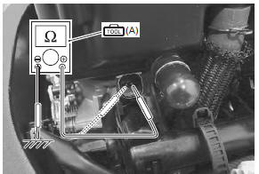
2 |
Special tool Tester knob indication
voltage ( Injector voltage battery voltage ((+) terminal: y/r – (–) terminal: ground)
Is the voltage ok? |
|
Open circuit in the y/r wire. |
 (a): 09900–25008 (multi
 )
)
 Dtc “c32” (p0201), “c33” (p0202), “c34” (p0203) or “c35” (p0204): primary
fuel injector circuit
malfunction
Dtc “c32” (p0201), “c33” (p0202), “c34” (p0203) or “c35” (p0204): primary
fuel injector circuit
malfunction
Detected condition and possible cause
Detected condition
Possible cause
Ckp signal is produced but fuel injector signal is
interrupted by 4 times or more continuity
...
 DTC “c40” (p0505 / p0506 / p0507): isc
valve circuit malfunction
DTC “c40” (p0505 / p0506 / p0507): isc
valve circuit malfunction
Detected condition and possible cause
Detected condition
Possible cause
C40/P0505
The circuit voltage of motor drive is
unusual.
Isc valve circuit open or ...
Other materials:
Precautions
Precautions for exhaust system
To avoid
the risk of being burned, do not touch the exhaust system when the
system is hot. Any
service on the exhaust system should be performed when the system is
cool.
Caution
make sure that the exhaust pipes and muffler ...
Headlight bulb and position light bulb
replacement
Caution
when you touch the bulb with your bare
hands, clean the bulb with a cloth moistened
with alcohol or soap water to prevent
premature bulb failure.
Low beam bulb
Remove the combination meter. Refer to “combination meter removal and
installation” in section 9c .
...
Specifications
Tightening torque specifications
Note
the specified tightening torque is described in the following.
“Body frame construction” “front footrest bracket construction”
“side-stand construction”
Reference: for the tightening torque of fastener not specified in this ...