Suzuki GSX-R 1000 Service Manual: Drive chain replacement
Use the special tool in the following procedures, to cut and rejoin the drive chain.
| Note when using the special tool, apply a small quantity of grease to the threaded parts of the special tool. |
Special tool
 : 09922–22711 (drive chain cutting
and joint
tool set)
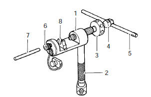
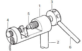
Drive chain cutting
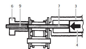
- Set up the special tool as shown in the figure.
|
| Note the tip of pin remover (7) should be positioned inside “a” approximately 5 mm (0.2 In) from the end face of pressure bolt [a] (3) as shown in the figure. |
|
- Place the drive chain link being disjointed on the chain holder (8) of the tool.
- Turn in both the adjuster bolt (6) and pressure bolt [a] (3) so that each of their end hole fits over the chain joint pin properly.
- Tighten the pressure bolt [a] (3) with the bar.
- Turn in the pressure bolt [b] (4) with the bar (5) and force out the drive chain joint pin (9).
| Caution continue turning in the pressure bolt [b] (4) until the joint pin should been completely pushed out of the chain. |
| Note after the joint pin (9) is removed, loosen the pressure bolt [b] (4) and then pressure bolt [a] (3). |
- Remove the joint pin (9) of the other side of joint plate.
| Caution never reuse joint pins, o-rings and plates. |
Drive chain connecting
 Do not use joint
|
Joint plate installation
- Set up the special tool as shown in the figure.
|
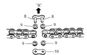
- Apply grease to the joint pins (8), o-rings (9) and plates (10).
| Caution replace the joint pins (8), o-rings (9) and plates (10) with new ones. |
- Connect both ends of the drive chain with the joint pins (8) inserted from the wheel side “a” as installed on the motorcycle.
Joint set part number did: 27620 – 40f20
- Apply grease on the recessed portion of the joint plate holder (3) and set the joint plate (10).
| Note when positioning the joint plate (10) on the tool, its stamp mark must face the joint plate holder (3) side. |
- Set the drive chain on the tool as illustrated and turn in the adjuster bolt (5) to secure the wedge holder and wedge pin (4).
- Turn in the pressure bolt [a] (6) and align two joint pins (8) properly with the respective holes of the joint plate (10).
- Turn in the pressure bolt [a] (6) further using the bar (7) to press the joint plate over the joint pins.
- Continue pressing the joint plate until the distance between the two joint plates comes to the specification.
Joint plate distance specification “a” 20.7 – 21.0 Mm (0.81 – 0.83 In)
| Caution if pressing of the joint plate makes the dimension out of specification excessively, the work must be carried out again by using new joint parts. |
Joint pin staking
- Set up the special tool as shown in the figure.
|
| Note before staking the joint pin, apply a small quantity of grease to the staking pin (5). |
- Stake the joint pin by turning (approximately 7/8 turn) the pressure bolt [a] (3) with the bar until the pin end diameter becomes the specified dimension.
Caution
|
Pin end diameter specification “a” did: 5.7 – 6.0 Mm (0.22 – 0.24 In)
- Adjust the drive chain slack, after connecting it.
Refer to “drive chain inspection and adjustment” in section 0b .
 Sprocket mounting drum dust seal / bearing removal and installation
Removal
Remove the rear wheel assembly. Refer to “rear wheel assembly removal
and installation” in section 2d .
Remove the rear sprocket mounting drum assembly
(1). Refer to “rear spr ...
 Specifications
Service data
Drive train
unit: mm (in) except ratio
Tightening torque specifications
Note
the specified tightening torque is described in the following.
“Drive chain related ...
Other materials:
Voltage check
If voltage is supplied to the circuit being checked, voltage
check can be used as circuit check.
With all connectors/couplers connected and voltage
applied to the circuit being checked, measure
voltage between each terminal and body ground.
If measurements were taken as shown ...
Water pump removal and installation
Removal
Note
before draining engine oil and engine coolant, inspect engine oil and
coolant leakage between the water pump and crankcase. If engine oil is
leaking, visually inspect the oil seal and o-ring. If engine coolant is
leaking, visually inspect the mechanical seal and s ...
Reporting safety defects
If you believe that your vehicle
has a defect which could cause a
crash or could cause injury or
death, you should immediately
inform the national highway traffic
safety administration (nhtsa)
in addition to notifying american
suzuki motor corp.
If nhtsa receives similar complaints,
it ma ...