Suzuki GSX-R 1000 Service Manual: Conrod and crankshaft inspection
Refer to “engine bottom side disassembly” (page 1d- 49).
Refer to “engine bottom side assembly” .
Conrod small end I.D.
Measure the conrod small end inside diameter using the small bore gauge.
If the conrod small end inside diameter exceeds the service limit, replace the conrod.
Special tool
 (a): 09900–20602 (dial gauge)
 (b): 09900–22401 (small bore gauge
(10 – 18
mm))
Conrod small end i.D.
Service limit: 15.040 Mm (0.5921 In)
Conrod big end side clearance
- Check the conrod big end side clearance using the thickness gauge.
Special tool
 (a): 09900–20803 (thickness gauge)
Conrod big end side clearance service limit: 0.30 Mm (0.012 In)
- If the clearance exceeds the limit, remove the conrod and measure the conrod big end width and crank pin width. Refer to “engine bottom side assembly” . If any of the measurements are out of specification, replace the conrod or crankshaft.
Special tool
 (b): 09900–20205 (micrometer (0 –
25 mm))
 (c): 09900–20605 (dial calipers (10
– 34
mm))
Conrod big end width standard: 19.95 – 20.00 Mm (0.7854 – 0.7874 In)
Crank pin width standard: 20.10 – 20.15 Mm (0.7913 – 0.7933 In)
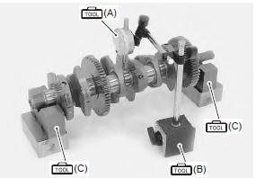
Crankshaft runout
Support the crankshaft using v-blocks as shown, with the two end journals resting on the blocks. Set up the dial gauge as shown, and rotate the crankshaft slowly to read the runout. Replace the crankshaft if the runout exceeds the service limit.
Special tool
 (a): 09900–20607 (dial gauge)
 (b): 09900–20701 (dial gauge chuck)
 (c): 09900–21304 (v blocks)
Crankshaft runout service limit: 0.05 Mm (0.002 In)
 Conrod crank pin bearing removal and
installation
Conrod crank pin bearing removal and
installation
Refer to “engine bottom side disassembly” (page 1d-
49).
Refer to “engine bottom side assembly” .
Removal
Remove the conrod crank pin bearings (1).
Note
do not remove the beari ...
 Conrod crank pin bearing inspection and
selection
Conrod crank pin bearing inspection and
selection
Refer to “engine bottom side disassembly” (page 1d-
49).
Refer to “engine bottom side assembly” .
Inspection
Inspect the bearing surfaces for any signs of fusion,
pitting, burn or flaws. If ...
Other materials:
Malfunction code and defective condition table
* : Immobilizer system equipped model only. ...
Front wheel dust seal / bearing removal and installation
Removal
Remove the front wheel assembly. Refer to “front wheel assembly removal
and installation” .
Remove the dust seals using the special tool.
Special tool
(a): 09913–50121 (oil
seal remover)
Remove the wheel bearings using the special tool.
Special tool
(b): 099 ...
Steering / steering damper removal and
installation
Removal
steering damper
Turn the ignition switch off.
Disconnect the steering damper solenoid coupler
(1).
Remove the lower bracket cover (2).
Remove the steering damper mounting nut (3) while
holding the lock-nut (4).
Remove the steering damper mounting bolt ( ...