Suzuki GSX-R 1000 Service Manual: Countershaft gear / driveshaft gear disassembly and assembly
Refer to “transmission removal” and “transmission installation” .
Disassembly
| Caution identify the position of each removed part. Organize the parts in their respective groups (i.E., Drive or driven) so that they can be reinstalled in their original positions. |
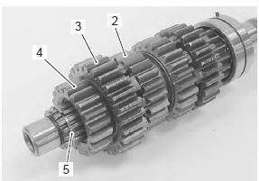
Countershaft
Disassemble the countershaft as shown in the transmission construction. Refer to “transmission construction” .
Pay attention to the following points:
- remove the 6th drive gear snap ring (1) from its groove and slide it towards the 3rd/4th drive gears (2).
Special tool
 : 09900–06104 (snap ring remover
(open
type))
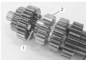
- Slide the 6th (3) and 2nd (4) drive gears toward the 3rd/4th drive gears (2), then remove the 2nd drive gear circlip (5).
- Remove the 2nd drive gear (4) and 6th drive gear (3).
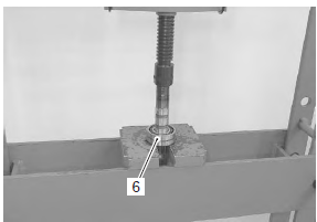
- Remove the countershaft bearing (6) using hydraulic press.
Driveshaft
- Disassembly the driveshaft as shown in the transmission construction. Refer to “transmission construction” .
Assembly
| Note when reassembling the transmission gears, attention must be given to the locations and positions of washers and snap rings. The cross sectional view shows the correct position of the gears, bushings, washers and snap rings. Refer to “transmission construction” . |
Caution
|
Note
|
 : Grease 99000–25010 (suzuki
super
grease “a” or equivalent)
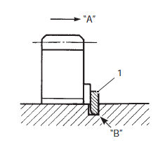
- When installing a new snap ring (1), pay attention to its direction. Fit it to the side where the thrust is as shown in the figure.
|
Driveshaft
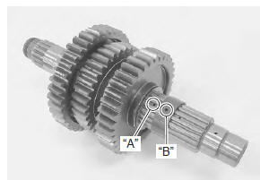
- When installing the gear bushings onto the driveshaft, align the shaft oil holes “a” with the bushing oil hole “b”.
Countershaft
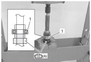
- Install the countershaft bearing (1) using a hydraulic press and special tool.
Special tool
 (a): 09913–70210 (bearing
installing set (10
– 75 Ô))
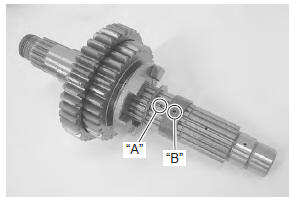
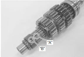
- When installing the gear bushing onto the countershaft, align the shaft oil hole “a” with the bushing oil hole “b”.
 Transmission construction
Countershaft
Driveshaft
...
 Transmission related parts inspection
Refer to “transmission removal” , “transmission installation” and
“countershaft gear / driveshaft gear disassembly and assembly” .
Gearshift fork to groove clearance
Note
the clear ...
Other materials:
Wiring diagram
Refer to “wire color symbols” in section 0a .
For e-02, 19, 24, 51
For e-03, 28
For e-14, 33
...
Break-in procedures
During manufacture only the best possible materials are
used and all machined parts are finished to a very high
standard but it is still necessary to allow the moving parts
to “break-in” before subjecting the engine to maximum
stresses. The future performance and reliability of the
engine depen ...
Maintenance schedule
It is very important to inspect and
maintain your motorcycle regularly.
Follow the guidelines in the
chart. The intervals between periodic
services in kilometers, miles
and months are shown. At the
end of each interval, be sure to
perlorm the maintenance listed.
Warning
Improper ...