Suzuki GSX-R 1000 Service Manual: Electrical parts connector / coupler
- Faulty fi system is often related to poor electrical contact of connector/coupler. Before servicing individual electronic part, check electrical contact of the connector/coupler.
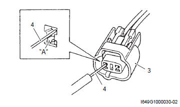
- When connecting a connector, be sure to push it in until a click is felt.
- With a lock type coupler, be sure to release the lock when disconnecting, and push it in fully to engage the lock when connecting.
- When disconnecting the coupler, be sure to hold the coupler body and do not pull the lead wires.
- Inspect each terminal on the connector/coupler for looseness or bending.
- Push in the coupler straightly. An angled or skewed insertion may cause the terminal to be deformed, possibly resulting in poor electrical contact.
- Inspect each terminal for corrosion and contamination. The terminals must be clean and free of any foreign material which could impede proper terminal contact.
- Before refitting the sealed coupler, make sure its seal rubber is positioned properly. The seal rubber may possibly come off the position during disconnecting work and if the coupler is refitted with the seal rubber improperly positioned, it may result in poor water sealing.
- Inspect each lead wire circuit for poor connection by shaking it by hand lightly. If any abnormal condition is found, repair or replace.
When taking measurements at electrical connectors using a tester probe, be sure to insert the probe from the wire harness side (rear) of the connector/coupler.
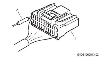
- Coupler
- Probe
- When connecting meter probe from the terminal side of the coupler (where connection from harness side not being possible), use extra care not to force and cause the male terminal to bend or the female terminal to open. Connect the probe as shown to avoid opening of female terminal. Never push in the probe where male terminal is supposed to fit.
- Check the male connector for bend and female connector for excessive opening. Also check the coupler for locking (looseness), corrosion, dust, etc.
- Coupler
- Probe
- Where male terminal fits
- Avoid applying grease or other similar material to connector/coupler terminals to prevent electric trouble.
 Precautions for electrical circuit service
When handling the electrical parts or servicing fi
system, observe the following points for the safety of the
systems. ...
 Clamp
Clamp
Clamp the wire harness at such positions as indicated in “wiring harness
routing diagram” in section 9a .
Bend the clamp properly so that the wire harness is
clamped securely.
...
Other materials:
Symbols
Listed in the table below are the symbols indicating instructions and other
information necessary for servicing.
The meaning of each symbol is also included in the table.
Abbreviations
A:
abdc: after bottom dead center
ac: alternating current
acl: air cleaner, air cleaner box
api: ame ...
Carrying a passenger
Before you invite someone to be a
passenger on your motorcycle,
you need to be thoroughly familiar
with motorcycle operation. Adjust
tire pressures and suspension
according to the tire pressure
and loading section and the suspension
section of this manual.
The passenger should always
hold ...
Turn signal / side-stand relay removal and
installation
Removal
Turn the ignition switch off.
Remove the frame cover assembly. Refer to “exterior parts removal and
installation” in section 9d .
Remove the turn signal/side-stand relay (1).
Installation
Install the turn signal/side-stand relay in the reverse
order of removal ...