Suzuki GSX-R 1000 Service Manual: Exterior parts removal and installation
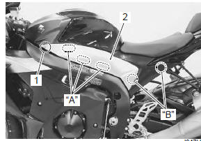
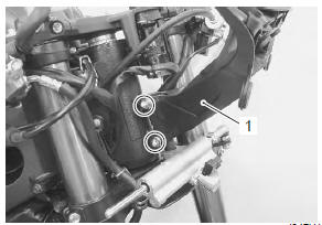
Side frame cover
Removal
| Note the left and right side frame covers are installed symmetrically and therefore the removal/installation procedure for one side is the same as that for the other side. |
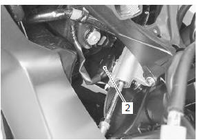
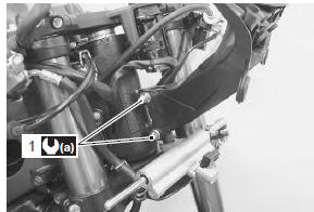
- Remove the bolt (1).
- Remove the side frame cover (2).
|
Installation
Installation is in the reverse order of removal.
Front seat
Removal
- Remove the side frame covers.
- Remove the front seat by removing the bolts.
Installation
- Slide the seat hooks into the seat hook retainers on the frame and tighten the bolts.
- Install the side frame covers.
Rear seat / seat tail cover
Removal
Remove the rear seat or seat tail cover with the ignition key.
Rear seat
Seat tail cover
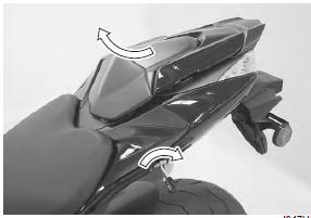
Installation
Slide the hook into the hook retainer and push down firmly until the rear seat/seat tail cover snaps into the locked position.
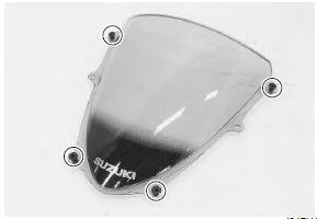
Windscreen
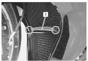
Removal
- Loosen the rear view mirror mounting nuts.
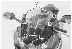
- Remove the windscreen (1) by removing the screws.
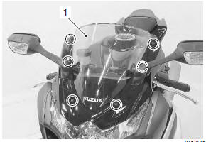
Installation
Install the windscreen in the reverse order of removal.
Pay attention to the following point:
- insert two nuts into the hole of cowling brace.
- Insert four nuts (top and bottom ones) into the windscreen.
- Tighten the screws.
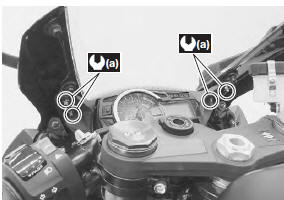
| Note the screws “a” are 3 mm shorter than the others |
- Tighten the rear view mirror mounting nuts to the specified torque.
Tightening torque rear view mirror mounting nut (a): 10 n·m (1.0 Kgf-m, 7.0 Lbf-ft)
Body cowling cover
Removal
- Remove the fasteners (8 pcs.).
- Remove the body cowling cover (1).
Installation
Install the body cowling cover in the reverse order of removal.
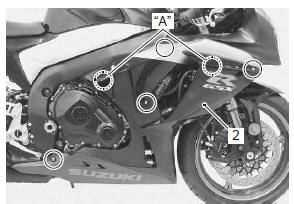
Side cowling
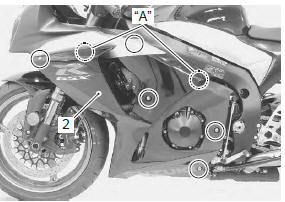
Removal
- Remove the fasteners and cowling bracket (1).
- Remove the bolts.
- Remove the side cowling (2). (Lh/rh)
|
Installation
Install side cowling in the reverse order of removal.
Pay attention to the following points:
- when installing the right side cowling, make sure that the fuel tank drain hose and breather hose are routed properly. Refer to “fuel tank drain hose and breather hose routing diagram” in section 1g .
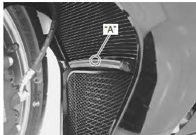
- When installing the bracket, set the punch mark “a” to the front and upper side.
Inner under cowling
Removal
| Note the left and right inner under cowlings are installed symmetrically and therefore the removal/installation procedure for one side is the same as that for the other side. |
- Remove the side cowling.
- Remove the inner under cowling (1).
Installation
Install the inner under cowling in the reverse order of removal.
Body cowling
Removal
- Remove the body cowling cover.
- Remove the left and right side cowlings.
- Remove the inner under cowlings.
- Remove the rear view mirror.
- Remove the windscreen.
- Remove the combination meter. Refer to “combination meter removal and installation” in section 9c .
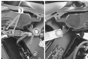
- Disconnect the turn signal lead wire couplers (1).
- Disconnect the steering damper lead wire coupler (2).
- Disconnect the lead wire couplers (3).
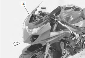
- Remove the air intake pipe bolts.
- Remove the screws.
- Remove the body cowling assembly (4) forward.
- Disassemble the body cowling assembly. Refer to “headlight removal and installation” in section 9b .
Installation
Install the body cowling in the reverse order of removal.
Pay attention to the following point:
- adjust the headlight beam if necessary. Refer to “headlight beam adjustment” in section 9b .
Intake pipe
Removal
- Remove the body cowling.
- Remove the intake pipes (1). (Lh & rh)
Installation
Install the intake pipes in the reverse order of removal.
Cowling brace
Removal
- Remove the body cowling.
- Remove the cowling brace (1).
Installation
Install the cowling brace in the reverse order of removal.
Pay attention to the following point:
- tighten the cowling brace mounting bolts (1) to the specified torque.
Tightening torque cowling brace mounting bolt (a): 23 n·m (2.3 Kgfm, 16.5 Lbf-ft)
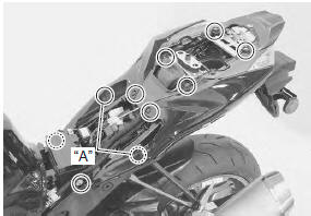
Frame cover
Removal
- Remove the front and rear seats.
- Remove the bolts and fasteners.
|
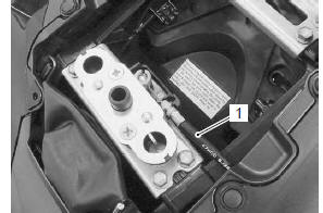
- Disconnect the seat lock cable (1).
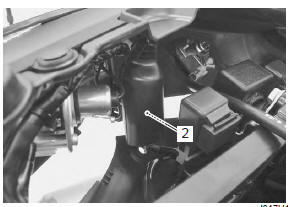
- Disconnect the rear combination light coupler (2).
- Remove the frame cover assembly from the frame.
- Disassemble the frame cover assembly. Refer to “rear combination light removal and installation” in section 9b .
Installation
Install the frame cover assembly in the reverse order of removal.
Front fender
Removal
Refer to “front fork removal and installation” in section 2b .
Installation
Refer to “front fork removal and installation” in section 2b .
Rear fender
Removal
Refer to “rear fender construction” .
Installation
Refer to “rear fender construction” .
 Fastener removal and installation
Type a
Removal
Depress the head of fastener center piece (1).
Pull out the fastener (2).
Installation
Let the center piece stick out toward the head so that
the pawls “a” clo ...
 Specifications
Tightening torque specifications
Note
the specified tightening torque is described in the following.
“Rear view mirror construction”
Reference: for the tightening torque of ...
Other materials:
Diagnostic information and procedures
Engine mechanical symptom diagnosis
Refer to “engine symptom diagnosis” in section 1a .
Compression pressure check
The compression pressure reading of a cylinder is a
good indicator of its internal condition.
The decision to overhaul the cylinder is often based on
the results of a compressio ...
Special tools and equipment
Recommended service material
Note
required service material is also described in the following.
“Throttle body components” “engine bottom side assembly”
Special tool
...
Lubrication points
Proper lubrication is important for smooth operation and long life of each
working part of the motorcycle.
Major lubrication points are indicated as follows.
Note
before lubricating each part, clean off any rusty spots
and wipe off any grease, oil, dirt or grime.
&nbs ...