Suzuki GSX-R 1000 Service Manual: DTC “c62” (p0443): evap system purge control solenoid valve circuit malfunction (e-33 only)
Detected condition and possible cause
|
Detected condition |
Possible cause |
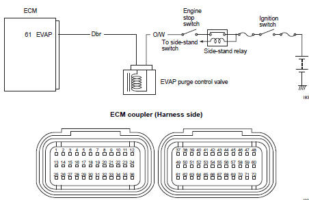
| Evap system purge control valve voltage is not input to ecm. |
|
Wiring diagram
Troubleshooting
| Caution when using the multi-circuit tester, do not strongly touch the terminal of the ecm coupler with a needle pointed tester probe to prevent terminal damage. |
| Note after repairing the trouble, clear the dtc using sds tool. Refer to “use of sds diagnosis reset procedures” . |
|
Step |
Action |
Yes |
No |
|
1 |
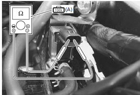
Special tool Tester knob indication resistance (Ω) Evap system purge control valve resistance approx. 32 Ω at 20 °c (68 °f) (terminal – terminal)
Is the resistance ok? |
Go to step 2. | Replace the evap system purge control with a new one. Refer to “evaporative emission control system removal and installation (only for e- 33)” in section 1b . |
|
2 |
Special tool Tester knob indication
voltage ( Evap system purge control valve voltage battery voltage ((+) terminal: o/w – (–) terminal: ground)
Is the voltage ok? |
|
Open or short circuit in the o/w wire. |
 (a): 09900–25008 (multi
 (a): 09900–25008 (multi
 )
)
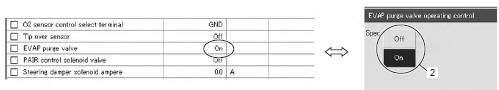
Active control inspection
- Set up the sds tool. (Refer to sds operation manual for further details.)
- Turn the ignition switch on.
- Click “evap purge valve operating control” (1).
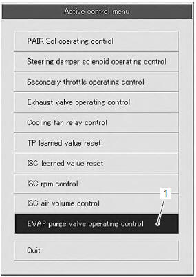
- Click each button (2). At this time, if an operating sound is heard from the evap system purge control valve, the function is normal.
 DTC “c60” (p0480): cooling fan relay
circuit malfunction
DTC “c60” (p0480): cooling fan relay
circuit malfunction
Detected condition and possible cause
Detected condition
Possible cause
Cooling fan relay signal is not input to ecm.
Cooling fan relay circuit open or short.
...
 DTC “c91” (p0500): vehicle speed sensor
circuit malfunction
DTC “c91” (p0500): vehicle speed sensor
circuit malfunction
Detected condition and possible cause
Detected condition
Possible cause
Speedometer does not receive signal from the vehicle
speed sensor for more than 6 sec. When the m ...
Other materials:
Front wheel components
Front axle
Brake disc bolt
Brake disc
Dust seal
Bearing
Spacer
Air valve
Front wheel
Wheel balancer
Front tire
Collar
Front axle bolt
18 N·m (1.8 Kgf-m,
13.0 Lbf-ft)
100 N·m
(10.0 Kgf-m, 72.5 Lbf-ft)
Apply ...
Special tools and equipment
Recommended service material
Note
required service material is also described in the following.
“Front brake master cylinder components” “rear brake master
cylinder components” “rear brake pedal construction”
Special tool
...
General description
Combination meter system description
This combination meter mainly consists of a stepping motor, lcd (liquid
crystal display) and leds (light emitting
diode).
The tachometer pointer is driven by the stepping motor.
The lcds indicate followings:
speed, odo / trip 1 / trip 2 / fuel reserve ...