Suzuki GSX-R 1000 Service Manual: DTC “c91” (p0500): vehicle speed sensor circuit malfunction
Detected condition and possible cause
|
Detected condition |
Possible cause |
| Speedometer does not receive signal from the vehicle speed sensor for more than 6 sec. When the motorcycle is running. Ecm does not receive signal from the vehicle speed sensor for more than 6 sec. When the motorcycle is running. Failure in communication between ecm and speedometer with reference to vehicle speed. |
|
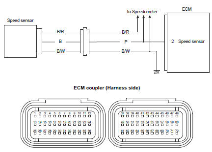
Wiring diagram
Troubleshooting
| Caution when using the multi-circuit tester, do not strongly touch the terminal of the ecm coupler with a needle pointed tester probe to prevent terminal damage. |
| Note after repairing the trouble, clear the dtc using sds tool. Refer to “use of sds diagnosis reset procedures” . |
|
Step |
Action |
Yes |
No |
|
|
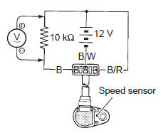
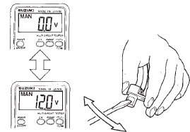
1 |
Special tool Tester knob indication
voltage (
Is the voltage ok? |
|
|
 (a): 09900–25008 (multi
 )
)
 DTC “c62” (p0443): evap system purge
control solenoid valve circuit malfunction
(e-33 only)
DTC “c62” (p0443): evap system purge
control solenoid valve circuit malfunction
(e-33 only)
Detected condition and possible cause
Detected condition
Possible cause
Evap system purge control valve voltage is not input to
ecm.
Evap system purge contro ...
 DTC “c93” (p1769): steering damper
solenoid valve circuit malfunction
DTC “c93” (p1769): steering damper
solenoid valve circuit malfunction
Detected condition and possible cause
Detected condition
Possible cause
C93
Steering damper control current does not flow to
the solenoid valve. With ig turned on ...
Other materials:
Throttle body inspection and cleaning
Refer to “throttle body disassembly and assembly” .
Cleaning
Some
carburetor cleaning chemicals,
especially dip-type soaking solutions, are
very corrosive and must be handled carefully.
Always follow the chemical manufacturer’s
instructions on proper use, handling and
sto ...
Special tools and equipment
Recommended service material
Note
required service material is also described in the following.
“Clutch control system components” “clutch components”
Special tool
...
Starting off
Warning
Riding this motorcycle at
excessive speed increases
your chances of losing control
of the motorcycle. This may
result in an accident.
Always ride within the limits of
your skills, your motorcycle,
and the riding conditions.
Warning
Remov ...