Suzuki GSX-R 1000 Service Manual: Fuel pressure inspection
|
|
Inspect the fuel pressure in the following procedures:
- lift and support the fuel tank. Refer to “fuel tank removal and installation” .
- Place a rag under the fuel feed hose (1) and remove the fuel feed hose.
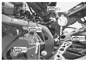
- Install the special tools between the fuel pump and fuel delivery pipe.
Special tool
 (a): 09940–40211 (fuel pressure
gauge
adapter)
 (b): 09940–40220 (fuel pressure
gauge
attachment)
 (c): 09915–77331 (oil pressure gauge
(1000
kpa))
 (d): 09915–74521 (adapter hose)
- Turn the ignition on and check for fuel pressure.
Fuel pressure approx. 300 Kpa (3.0 Kgf/cm2, 43 psi)
If the fuel pressure is lower than the specification, check for the followings:
- fuel hose leakage
- clogged fuel filter
- pressure regulator
- Fuel pump
If the fuel pressure is higher than the specification, check for the followings:
- fuel pump
- pressure regulator
- Remove the special tools.
 Before Before
removing the special tools, turn the ignition switch off and release the fuel pressure slowly. |
- Reinstall the fuel tank. Refer to “fuel tank removal and installation” .
| Note connect the fuel feed hose to the fuel pump until it locks securely (a click is heard). |

 Fuel pump inspection
Turn the ignition switch on and check that the fuel pump
operates for a few seconds.
If the fuel pump motor does not make operating sound, inspect the fuel pump
circuit connections or inspect th ...
Other materials:
Clutch control system components
Push rod
Clutch release camshaft
Clutch release arm
Clutch cable
1 N·m (0.1 Kgf-m, 0.7
Lbf-ft)
6 N·m
(0.6 Kgf-m, 4.5 Lbf-ft)
10 N·m
(1.0 Kgf-m, 0.7 Lbf-ft)
Apply grease
Do not reuse.
...
Rear shock absorber disposal
Refer to “rear shock absorber removal and installation” .
The rear shock absorber unit contains high-pressure
nitrogen gas.
Mishandling can cause explosion.
Keep away from fire and heat. High gas
pressure caused by heat can cause an
explosion.
Release gas ...
Fuel
Your motorcycle requires premium
unleaded gasoline with a
minimum pump octane rating of
90 ((r+m)/2 method). In some
areas, the only fuels that are
available are oxygenated fuels.
Oxygenated fuels which meet the
minimum octane requirement and
the requirements described below
may be used i ...