Suzuki GSX-R 1000 Service Manual: Balancer shaft journal bearing inspection and selection
Refer to “engine bottom side disassembly” (page 1d- 49).
Refer to “engine bottom side assembly” .
Inspection
Inspect the bearing surfaces for any signs of fusion, pitting, burn or flaws. If any, replace them with a specified set of bearings.
Selection
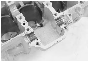
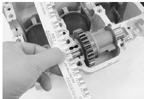
- Place the plastigauge axially along the balancer shaft journal as shown.
Special tool (a): 09900–22301 (plastigage (0.025 – 0.076 Mm))
| Caution never rotate the balancer shaft when a piece of plastigauge is installed. |
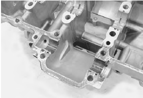
- Mate the lower crankcase with the upper crankcase, and tighten the crankcase bolts (m8) and crankshaft journal bolts (m9) to the specified torque.
Tightening torque crankshaft journal bolt (m9): 18 n·m (1.8 Kgf-m, 13.0 Lbf-ft) then turn in 50° crankcase bolt (m8) (initial): 15 n·m (1.5 Kgf-m, 11.0 Lbf-ft) crankcase bolt (m8) (final): 26 n·m (2.6 Kgf-m, 19.0 Lbf-ft) crankcase bolt (m6): 12 n·m (1.2 Kgf-m, 8.5 Lbfft)
- Remove the lower crankcase and measure the width of the compressed plastigauge using the envelope scale. This measurement should be taken at the widest part of the compressed plastigauge. If the oil clearance exceeds the service limit, select the specified bearings from the bearing selection table.
Balancer shaft journal oil clearance standard: 0.028 – 0.052 Mm (0.0011 – 0.0020 In) service limit: 0.080 Mm (0.0031 In)
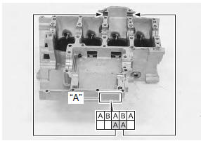
- Check the corresponding crankcase journal i.D.
Code number “a”, [a], [b] or [c] which is stamped on the rear of upper crankcase.
Bearing selection table
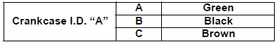
Crankcase I.D. Specification
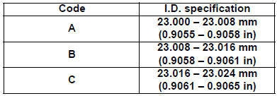
Balancer shaft journal o.D. Specification 19.992 – 20.000 Mm (0.7871 – 0.7874 In)
Bearing thickness specification
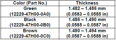
| Note the balancer shaft journal bearings on upper and lower crankcases are the same. |
 Balancer shaft journal bearing removal and
installation
Balancer shaft journal bearing removal and
installation
Refer to “engine bottom side disassembly” (page 1d-
49).
Refer to “engine bottom side assembly” .
Removal
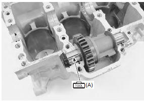
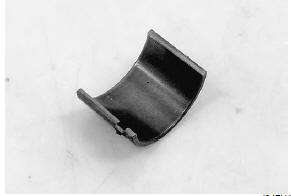
Remove the balancer shaft journal bearings (1).
Note
do not remove the ...
 Conrod crank pin bearing removal and
installation
Conrod crank pin bearing removal and
installation
Refer to “engine bottom side disassembly” (page 1d-
49).
Refer to “engine bottom side assembly” .
Removal
Remove the conrod crank pin bearings (1).
Note
do not remove the beari ...
Other materials:
Stp sensor removal and installation
Removal
Remove the throttle body. Refer to “throttle body
removal and installation” in section 1d (page 1d-
10).
Remove the stp sensor (1) with the special tool.
Special tool
: 09930–11950 (torx wrench (5 mm))
Note
prior to disassembly, mark the stp sensor’s
origina ...
Gearshift shaft oil seal / bearing removal and installation
Removal
Remove the gearshift shaft. Refer to “gearshift shaft / gearshift cam
plate removal and installation” .
Remove the gearshift shaft oil seal (1).
Remove the bearings (2) and (3) with the special
tools.
Special tool
(a): 09921–20210 (bearing remover
(12
mm))
...
Turn signal switch inspection
Inspect the turn signal switch in the following
procedures:
remove the air cleaner box. Refer to “air cleaner box removal and
installation” in section 1d .
Disconnect the left handlebar switch coupler (1).
(Yellow)
Inspect the turn signal switch for continuity wit ...