Suzuki GSX-R 1000 Service Manual: Front brake master cylinder assembly removal and installation
Removal
- Drain brake fluid. Refer to “brake fluid replacement” .
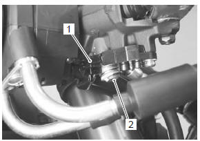
- Disconnect the front brake light switch coupler (1).
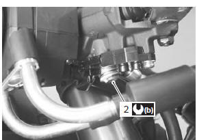
- Place a rag underneath the brake hose union bolt (2) on the master cylinder to catch any spilt brake fluid.
- Remove the brake hose union bolt (2).
- Remove the master cylinder assembly.
Installation
Install the front brake master cylinder in the reverse order of removal. Pay attention to the following points:
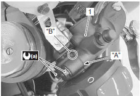
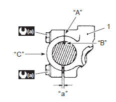
- when installing the master cylinder (1) onto the handlebar, align the master cylinder holder’s mating surface “a” with the punch mark “b” on the handlebar and tighten the upper holder bolt first.
Tightening torque front brake master cylinder holder bolt (upper and lower) (a): 10 n·m (1.0 Kgf-m, 7.0 Lbf-ft)
|
- After setting the brake hose union to the stopper, tighten the union bolt (2) to the specified torque.
| Caution the seal washers should be replaced with the new ones to prevent fluid leakage. |
Tightening torque brake hose union bolt (b): 23 n·m (2.3 Kgf-m, 16.5 Lbf-ft)
- Bleed air from the master cylinder in the same manner as caliper side.
| Note if air is trapped in the master cylinder, bleed air from the master cylinder first. |
Tightening torque air bleeder valve (front master cylinder): 6 n·m ( 0.6 Kgf-m, 4.5 Lbf-ft)
- Bleed air from brake system. Refer to “air bleeding from brake fluid circuit” .
 Front brake master cylinder components
Reservoir cap
Plate
Diaphragm
Reservoir tank
Master cylinder
Dust boot
Piston set
Brake lever
Brake lever pivot bolt
Brake lever pivot bolt lock ...
 Front brake master cylinder / brake lever disassembly and assembly
Refer to “front brake master cylinder assembly removal and installation” .
Disassembly
Remove the reservoir cap (1), plate (2), diaphragm
(3) and reservoir tank (4).
Remove the brake ...
Other materials:
Front wheel dust seal / bearing removal and installation
Removal
Remove the front wheel assembly. Refer to “front wheel assembly removal
and installation” .
Remove the dust seals using the special tool.
Special tool
(a): 09913–50121 (oil
seal remover)
Remove the wheel bearings using the special tool.
Special tool
(b): 099 ...
Rear brake components
Rear brake caliper
Piston seal
Dust seal
Piston
Rear caliper bracket
Rear brake pad set
Rear brake disc
Brake pad spring
6
N·m (0.6 Kgf-m, 4.5 Lbf-ft)
27 N·m
(2.7 Kgf-m, 19.5 Lbf-ft)
12 N·m
(1.2 Kgf-m, 8.5 Lbf-ft)
17 N·m ...
Generator inspection
Generator coil resistance
Remove the left side cowling. Refer to “exterior parts removal and
installation” in section 9d .
Disconnect the generator coupler (1).
Measure the resistance between the three lead
wires.
If the resistance is out of specified value, replace the
...