Suzuki GSX-R 1000 Service Manual: Front brake master cylinder / brake lever disassembly and assembly
Refer to “front brake master cylinder assembly removal and installation” .
Disassembly
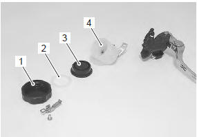
- Remove the reservoir cap (1), plate (2), diaphragm (3) and reservoir tank (4).
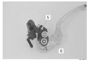
- Remove the brake light switch (5) and brake lever (6).
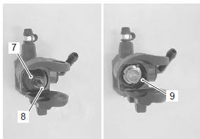
- Remove the dust boot (7) and push rod (8).
- Remove the snap ring (9).
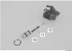
- Remove the following parts from the master cylinder.
- Piston (10)
- return spring (11)
- return spring guide (12)
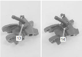
- Remove the dust rubber (13) and snap ring (14).
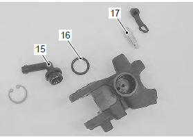
- Remove the connector (15), o-ring (16) and air bleeder valve (17).
Assembly
Assemble the master cylinder in the reverse order of disassembly. Pay attention to the following points:
Caution
|
Bf: brake fluid (dot 4)
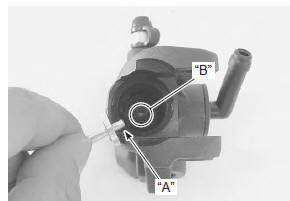
- When install the spring guide, insert the spring guide end “a” into the hole “b” of the master cylinder
- Apply grease to the push rod.
 : Grease 99000–25100 (suzuki
silicone
grease or equivalent)
- Apply grease to the brake lever pivot bolt.
 : Grease 99000–25100 (suzuki
silicone
grease or equivalent)
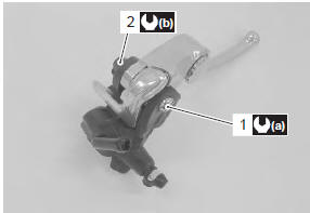
- Tighten the pivot bolt (1) and lock-nut (2) to the specified torque.
Tightening torque brake lever pivot bolt (a): 1 n·m (0.1 Kgf-m, 0.5 Lbf-ft) brake lever pivot bolt lock-nut (b): 6 n·m (0.6 Kgf-m, 4.5 Lbf-ft)
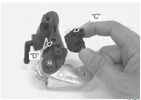
- When installing the brake light switch, align the projection “c” on the switch with the hole “d” in the master cylinder.
 Front brake master cylinder assembly removal and installation
Removal
Drain brake fluid. Refer to “brake fluid replacement” .
Disconnect the front brake light switch coupler (1).
Place a rag underneath the brake hose union bolt (2)
on the m ...
 Front brake master cylinder parts inspection
Refer to “front brake master cylinder / brake lever disassembly and assembly”
.
Master cylinder
Inspect the master cylinder bore for any scratches or
other damage
Piston / rubber parts
Insp ...
Other materials:
Fi system troubleshooting
Customer complaint analysis
Record details of the problem (failure, complaint) and how it occurred as
described by the customer. For this purpose,
use of such an inspection form such as following will facilitate collecting
information to the point required for proper
analysis and diagnosis.
...
Steering damper maintenance
Keep the steering damper
shaft 1 clean at all times.
Wipe off any oil residue with a
cloth.
Do not confuse the grease-like
residue on the steering damper's
shaft with an oil leak. Collection of
this residue is normal and is from
oil seal lubricant used in the
damper.
Yo ...
Specifications
Service data
Electrical
unit: mm (in)
Tightening torque specifications
Reference: for the tightening torque of fastener not specified in this
section, refer to “tightening torque list” in section 0c . ...