Suzuki GSX-R 1000 Service Manual: General description
Combination meter system description
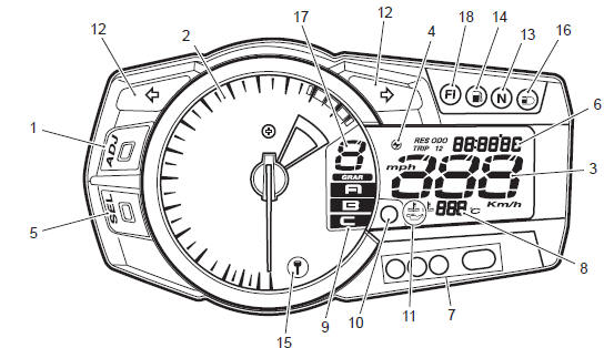
This combination meter mainly consists of a stepping motor, lcd (liquid crystal display) and leds (light emitting diode).
The tachometer pointer is driven by the stepping motor.
The lcds indicate followings: speed, odo / trip 1 / trip 2 / fuel reserve trip / clock / fi (dtc) / lap time counter / panel light brightness, gear position, engine rpm indicator, oil pressure indicator, engine coolant temperature and drive mode position.
Led (light emitting diode)
Led is used for the illumination light and each indicator light.
Led is maintenance free. Led is less power consuming and more resistant to vibration resistance compared to the bulb.
Engine rpm indicator light
This speedometer is equipped the engine revolution indicator light. The engine revolution indicator light is adjustable from 5 000 – 13 750 r/min. (From 5 000 r/min to 10 000 r/min, every 250 r/min and 10 000 r/min to 13 750 r/min, every 50 r/min: initial setting: 11 000 r/min)
|


Other materials:
Tampering with noise control system prohibited
Federal law prohibits the following
acts or the causing there of;
The removal or rendering inoperative
by any person other
than for purposes of maintenance,
repair, or replacement,
of any device or element of
·design incorporated into any
new vehicle for the purpose of
noise ...
Rear brake hose routing diagram
Hose clamp
: face the clamp end backward.
Stopper
: after the brake hose union has contacted
to the stopper, tighten the union bolt.
Brake pad pin
Plug
Caliper sliding pin b
Caliper sliding pin a
White marking
Yellow marking
Pass the
...
Rear shock absorber adjustment
After installing the rear suspension, adjust the spring
pre-load and damping force as follows:
Spring pre-load adjustment
The set length 179.3 Mm (7.06 In) provides the
maximum spring pre-load.
The set length 189.3 Mm (7.45 In) provides the
minimum spring pre-load.
Std position
184.3 ...