Suzuki GSX-R 1000 Service Manual: Handlebar removal and installation
Removal
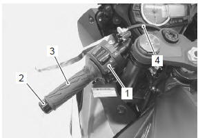
- Remove the following parts from the left handlebar.
- left handlebar switch box (1)
- handlebar balancer (2)
- grip rubber (3)
- clutch cable (4)
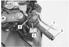
- Remove the following parts from the right handlebar.
- right handlebar switch box (5)
- handlebar balancer (6)
- throttle grip (7)
- front brake master cylinder (8)
| Caution do not turn the front brake master cylinder upside down. |
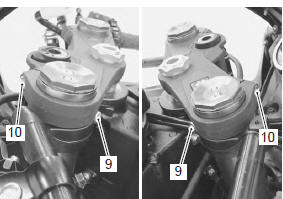
- Loosen the handlebar clamp bolts (9) and front fork upper clamp bolts (10).
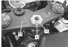
- Remove the steering stem head nut (11) and washer (12).
- Remove the steering stem upper bracket assembly (13).
| Note place a rag under the steering stem upper bracket to prevent scratching the body cowling and the combination meter. |
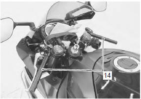
- Remove the handlebars (14) upward.
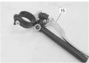
- Remove the clutch lever assembly (15) from the left handlebar.
Installation
Install the handlebars in the reverse order of removal.
Pay attention to the following points:
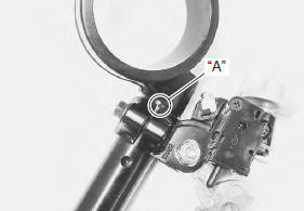
- when installing the clutch lever assembly to the left handlebar, align the slit of lever holder with the punch mark “a”.
- Install the handlebars temporarily to the front forks.
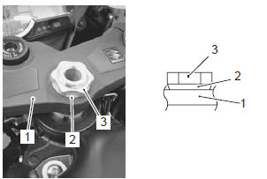
- Install the upper bracket (1), washer (2) and steering stem head nut (3) temporarily.
| Note face the chamfer side of the washer downward. |
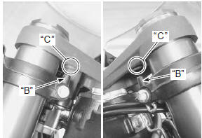
- Insert the protrusion “b” of the handlebar into the hole “c” of the steering stem upper bracket.
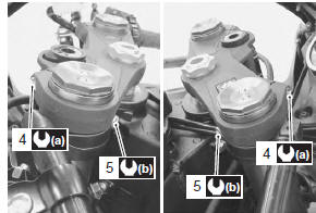
- Tighten the front fork upper clamp bolts (4) and handlebar clamp bolts (5) to the specified torque.
Tightening torque front fork upper clamp bolt (a): 23 n·m (2.3 Kgfm, 16.5 Lbf-ft) handlebar clamp bolt (b): 23 n·m (2.3 Kgf-m, 16.5 Lbf-ft)
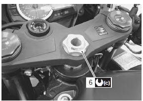
- Tighten the steering stem head nut (6) to the specified torque.
Tightening torque steering stem head nut (c): 90 n·m (9.0 Kgf-m, 65.0 Lbf-ft)
- Install the front brake master cylinder. Refer to “front brake master cylinder assembly removal and installation” in section 4a .
- Apply grease to the end of the throttle cables and cable pulley.
 : Grease 99000–25010 (suzuki
super
grease “a” or equivalent)
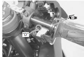
- Insert the projection “d” of the right handlebar switch box into the hole of the right handlebar.
- Apply a handle grip bond “e” onto the left handlebar before installing the handlebar grip.
 : Handle grip bond (handle
grip bond
(commercially available))
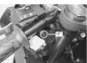
- Insert the projection “f” of the left handlebar switch box into the hole of the left handlebar.
- After installing the steering, the following adjustments are required before driving.
- Throttle cable routing (refer to “throttle cable routing diagram” in section 1d )
- clutch cable routing (refer to “throttle cable routing diagram” in section 1d )
- throttle cable play (refer to “throttle cable play inspection and adjustment” in section 1d )
- clutch cable play (refer to “clutch cable play inspection and adjustment” in section 0b )
 Handlebar components
Throttle grip
Grip rubber
Right handlebar switch box
Left handlebar switch box
Right handlebar
Left handlebar
Handlebar expander
Handlebar balancer
...
 Handlebars inspection
Refer to “handlebar removal and installation” (page 6b-
2).
Inspect the handlebars for distortion and damage.
If any defect is found, replace the handlebar with a new
one.
...
Other materials:
Clamp
Clamp the wire harness at such positions as indicated in “wiring harness
routing diagram” in section 9a .
Bend the clamp properly so that the wire harness is
clamped securely.
In clamping the wire harness, use care not to allow it
to hang down.
Do not use wire or an ...
Special tools and equipment
Recommended service material
Note
required service material is also described in the following.
“Front wheel components” “front wheel assembly construction” “rear
wheel components” “rear wheel assembly construction”
Special tool
...
Exhaust control system operation
The excs is operated by the signal supplied from the ecm. The open/close
operation of the excv is performed by
the excva which is controlled by the ecm by changing the current direction of
the actuator motor. The position
sensor (incorporated in the excva) detects the excva movement by measuri ...