Suzuki GSX-R 1000 Service Manual: Steering tension adjustment
Check the steering movement in the following procedures:
- by supporting the motorcycle with a jack, lift the front wheel unit is off the floor 20 – 30 mm (0.8 – 1.2 In).
- Remove the steering damper. Refer to “steering damper construction” .
- Check to make sure that the cables and wire harnesses are properly routed.
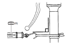
- With the front wheel in the straight ahead state, hitch the spring scale (special tool) on one handlebar grip end as shown in the figure and read the graduation when the handlebar starts moving.
Initial force 200 – 500 grams
Special tool

(a):
09940–92720 (spring scale)
- Do the same on the other grip end.
- If the initial force read on the scale when the handlebar starts turning is either too heavy or too light, adjust it till it satisfies the specification.
- first, loosen the front fork upper clamp bolts, handlebar clamp bolts, steering stem head nut and steering stem lock-nut, and then adjust the steering stem nut by loosening or tightening it.
- tighten the steering stem lock-nut, stem head nut, handlebar clamp bolts and front fork upper clamp bolts to the specified torque and re-check the initial force with the spring scale according to the previously described procedure.
- if the initial force is found within the specified range, adjustment has been completed.
| Note hold the front fork legs, move them back and forth and make sure that the steering is not loose. |
 Steering stem bearing removal and installation
Removal
Remove the steering stem upper bearing and steering stem lower bracket.
Refer to “steering / steering damper removal and installation” .
Remove the steering stem lower bearing i ...
 Specifications
Tightening torque specifications
Note
the specified tightening torque is described in the following.
“Handlebar components” “steering components” “steering
damper c ...
Other materials:
Ckp sensor removal and installation
Removal
Remove the clutch cover. Refer to “clutch removal” in section 5c .
Remove the ckp sensor (1).
Installation
Install the ckp sensor in the reverse order of removal.
Refer to “clutch installation” in section 5c .
Iap sensor inspection
Refer to “dtc “c13” (p0105-h/l): ia ...
Front brake master cylinder assembly removal and installation
Removal
Drain brake fluid. Refer to “brake fluid replacement” .
Disconnect the front brake light switch coupler (1).
Place a rag underneath the brake hose union bolt (2)
on the master cylinder to catch any spilt brake fluid.
Remove the brake hose union bolt (2).
...
Evaporative emission control system
diagram (only for e-33)
Fuel tank
Fuel-vapor separator
Fuel pump
Fuel feed hose
Fuel shut-off valve
Iap sensor
Surge hose
Evap canister
Purge hose
Evap system purge control solenoid valve
Fue
Hc vapor
Fresh air
Vacuum
...