
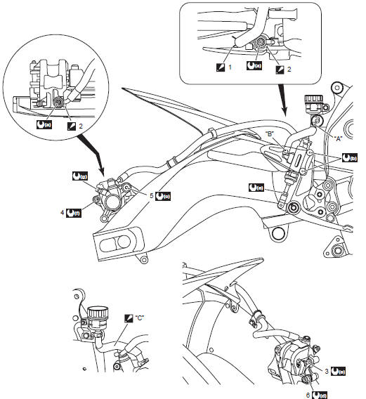
Suzuki GSX-R 1000 Service Manual: Rear brake hose routing diagram
|
 Hose clamp
 Stopper
 Pass the
 23 N·m (2.3 Kgf-m,
 10 N·m
 27 N·m
 12 N·m
 17 N·m
 2.5 N·m
 6 N·m
6 N·m
 Front brake hose routing diagram
Hose clamp
: clamp end should face downward.
Stopper
: after the brake hose union has contacted to the stopper, tighten
the union bolt.
Hose guide
: pass t ...
 Diagnostic information and procedures
Brake symptom diagnosis
...
Other materials:
Clamp
Clamp the wire harness at such positions as indicated in “wiring harness
routing diagram” in section 9a .
Bend the clamp properly so that the wire harness is
clamped securely.
In clamping the wire harness, use care not to allow it
to hang down.
Do not use wire or an ...
Cam chain guide / cam chain tensioner
removal and installation
Removal
Remove the cylinder head cover. Refer to “engine top side disassembly” .
Remove the cam chain guide no. 2 (1).
Remove the cylinder head. Refer to “engine top side disassembly”
and “engine bottom side disassembly” .
Remove the starter clutch. Refer to “s ...
Battery runs down quickly
Troubleshooting
Step
Action
Yes
No
1
Check accessories which use excessive amounts of
electricity.
Are accessories being installed?
Remove accessories.
Go to step 2.
2
Check the battery for current leakage. Refer to “battery
cu ...