Suzuki GSX-R 1000 Service Manual: Schematic and routing diagram
Refer to “wire color symbols” in section 0a .
Component location
Starting system components location
Refer to “electrical components location” in section 0a .
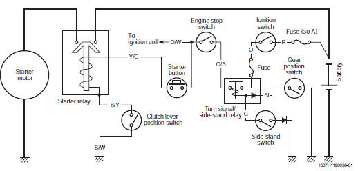
 Starting system
...
 Diagnostic information and procedures
Starting system symptom diagnosis
Condition
Possible cause
Correction / reference item
Engine does not turn
though the starter motor
runs
Faulty starter clu ...
Other materials:
DTC “c14” (p0120-h/l): tp sensor circuit
malfunction
Detected condition and possible cause
Detected condition
Possible cause
C14
Output voltage is not within the following
range.
Difference between actual throttle opening
and opening calculated by ecm is larger
than specified value.
0.2 V ≤ Sensor ...
Exhaust control system construction
Excv cable no. 1 (Cl)
Excv cable no. 2 (Op)
When
loosening or tightening the pulley bolt, be sure to fix the
pulley with an adjustable wrench, or excva may get damaged.
5 N·m (0.5 Kgf-m, 3.5 Lbf-ft)
42 – 43 Mm (1.65 – 1.69 In)
60 – 61 Mm (2.36 – ...
Isc valve reset
When removing or replacing the throttle body assembly,
reset the isc valve learned value in the following
procedures:
turn the ignition switch on position.
Set up the sds tools. (Refer to the sds operation
manual for further details.)
Click “active control”.
Click “is ...