
Suzuki GSX-R 1000 Service Manual: Specifications
Service data
Brake unit: mm (in)

Tightening torque specifications
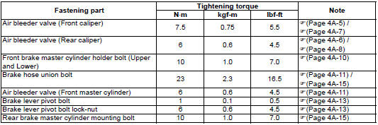
| Note the specified tightening torque is described in the following. “Front brake hose routing diagram” “rear brake hose routing diagram” “front brake master cylinder components” “rear brake master cylinder components” “rear brake pedal construction” |
Reference
: for the tightening torque of fastener not specified in this section, refer to “tightening torque list” in section 0c .
 Rear brake pedal removal and installation
Removal
Remove the master cylinder assembly. Refer to “rear brake master
cylinder assembly removal and installation” .
Disconnect the rear brake light switch lead wire coupler. Refer to ...
 Special tools and equipment
Recommended service material
Note
required service material is also described in the following.
“Front brake master cylinder components” “rear brake master
cylinder com ...
Other materials:
Excva pulley inspection
Inspect the excva pulley in the following procedures:
remove the excva pulley. Refer to “excv cable removal and installation”
.
Visually inspect the excva pulley for wear and
damage. If there is anything unusual, replace the
pulley with a new one.
Install the pulle ...
Front fork disassembly and assembly
Refer to “front fork removal and installation” (page 2b-
2).
Note
the right and left front forks are installed
symmetrically and therefore the disassembly
procedure for one side is the same as that for
the other side.
Disassembly
Turn the spring pre-load adjuster (1) t ...
Side stand
An interlock switch is provided to
cut off the ignition circuit when the
side stand is down and the transmission
is in any gear other than
neutral.
The side stand/ignition interlock
switch works as follows:
if the side stand is down and
the transmission is in gear, the
engine ...