Suzuki GSX-R 1000 Service Manual: Stp sensor adjustment
Adjust the stp sensor in the following procedures:
- remove the air cleaner box cover. Refer to “air cleaner element removal and installation” in section 1d .
- Disconnect the stva lead wire coupler (1).
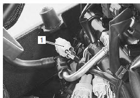
- Insert the needle pointed probes to the stp sensor coupler (between y/w and b/br wires).
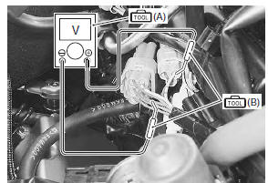
- Turn the ignition switch on.
- Close the secondary throttle valve by finger and measure the stp sensor output voltage.
Special tool
 (a): 09900–25008 (multi circuit
tester set)
 (b): 09900–25009 (needle-point probe
set)
Tester knob indication
voltage ( )
)
Stp sensor output voltage st valve is fully closed: approx. 0.7 V ((+): y/w – (–): b/br)
- Move the throttle body upward by loosing the throttle body mounting screws.
- Loosen the stp sensor mounting screw using the special tool and adjust the stp sensor until the output voltage comes within the specified value.
Special tool
: 09930–11950 (torx wrench (5 mm))
- Tighten the stp sensor mounting screw to the specified torque.
Tightening torque stp sensor mounting screw: 3.5 N·m (0.35 Kgfm, 2.5 Lbf-ft)
- Reinstall the removed parts.
 To sensor removal and installation
Removal
Remove the ap sensor. Refer to “ap sensor removal and installation” .
Disconnect the coupler (1) and remove the to
sensor (2).
Installation
Install the to sensor in the r ...
 Stp sensor removal and installation
Removal
Remove the throttle body. Refer to “throttle body
removal and installation” in section 1d (page 1d-
10).
Remove the stp sensor (1) with the special tool.
Special tool
: 099 ...
Other materials:
Using the testers
Incorrectly connecting the (+) and (.) Probes may
cause the inside of the tester to be burned.
If the voltage and current are not known, make
measurements using the highest range.
When measuring the resistance with the multi-circuit
tester (1), ∞ will be shown as 10.00 ...
Cushion rod inspection
Refer to “cushion rod removal and installation” .
Collar and spacer
Remove the collar and spacer from the cushion rod.
Inspect the collar and spacer for any flaws or other
damage. If any defects are found, replace it with a
new one.
Cushion rod bearing
Insert the collar a ...
Chassis bolt and nut inspection
Tighten chassis bolt and nut
initially at 1 000 km (600 miles, 2 months) and every
6 000 km (4 000 miles, 12 months) thereafter
Check that all chassis bolts and nuts are tightened to
their specified torque.
Steering stem
lock-nut 80 n·m (8.0 Kgf-m, 58.0 Lbf-ft)
Stee ...