Suzuki GSX-R 1000 Service Manual: Self-diagnostic procedures
Use of mode select switch
Note
|
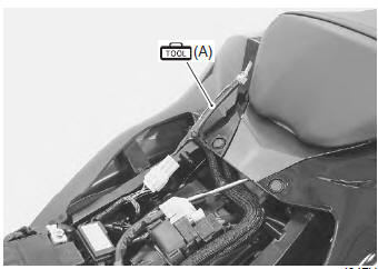
- Remove the front seat. Refer to “exterior parts removal and installation” in section 9d (page 9d- 6).
- Connect the special tool to the mode select switch coupler.
Special tool
 (a): 09930–82720 (mode selection
switch)
- Start the engine or crank the engine for more than 4 seconds.
- Turn the special tool’s switch on.
- Check the dtc to determine the malfunction part.
Refer to “dtc table” .
Special tool
(a): 09930–82720 (mode selection
switch)
- After repairing the trouble, turn off the ignition switch and turn on again. If dtc is indicated (c00), the malfunction is cleared.
Note
|
- Turn the ignition switch off and disconnect the special tool from the mode select switch coupler.
- Reinstall the front seat.
Use of sds
Note
|
- Remove the front seat. Refer to “exterior parts removal and installation” in section 9d (page 9d- 6).
- Set up the sds tools. (Refer to the sds operation manual for further details.)
Special tool
 (a): 09904–41010 (suzuki diagnostic
system set)
 (b): 99565–01010–020 (cd-rom
ver.20)
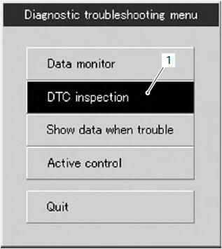
- Click the dtc inspection button (1).
- Start the engine or crank the engine for more than 4 seconds.
- Check the dtc to determine the malfunction part.
Refer to “dtc table” .
Note
|
- After repairing the trouble, clear to delete history code (past dtc). Refer to “use of sds diagnosis reset procedures” .
- Close the sds tool and turn the ignition switch off.
- Disconnect the sds tool and install the front seat.

 Use of sds diagnosis reset procedures
Note
the malfunction code is memorized in the
ecm also when the lead wire coupler of any
sensor is disconnected. Therefore, when a
lead wire coupler has been disconnected at
the ...
Other materials:
Component location
Electrical components location
Ignition switch/immobilizer antenna
Iat sensor
Secondary fuel injector
Primary fuel injector
Iap sensor
Evap system purge control solenoid valve
Fuel pump relay
Turn signal/side-stand relay
Cooling fan relay
Ect ...
Engine sprocket removal and installation
Removal
Remove the gearshift link arm (1) from the gearshift
shaft.
Note
mark the gearshift shaft head at which the
gearshift link arm slit set for correct
reinstallation.
Remove the speed sensor (2).
Remove the engine sprocket cover (3).
Support the ...
Procedure for returning
to service
Clean the entire motorcycle.
Remove the oily rags from the
air cleaner intake and muffler
outlet.
Drain all the engine oil. Install
a new oil filter and fill the
engine with fresh oil as outlined
in this manual.
Remove the spark plugs. Turn
the engine a few tim ...