Suzuki GSX-R 1000 Service Manual: Engine sprocket removal and installation
Removal
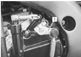
- Remove the gearshift link arm (1) from the gearshift shaft.
| Note mark the gearshift shaft head at which the gearshift link arm slit set for correct reinstallation. |
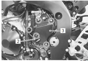
- Remove the speed sensor (2).
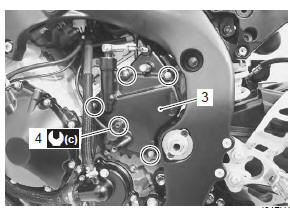
- Remove the engine sprocket cover (3).
- Support the motorcycle with a jack or wooden block.
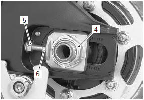
- Loosen the rear axle nut (4) and left and right chain adjuster lock-nuts (5).
- Loosen the chain adjusters (6) to provide additional chain slack.
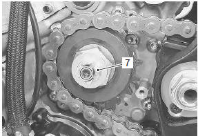
- Remove the speed sensor rotor (7) by removing its bolt while depressing the rear brake pedal.
- Remove the engine sprocket nut (8) while depressing the rear brake pedal.
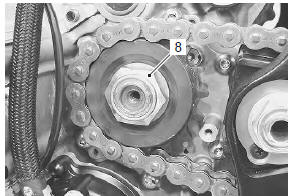
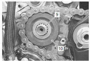
- Remove the washer (9).
- Remove the engine sprocket (10).
Installation
Install the engine sprocket in the reverse order of removal. Pay attention to the following points:
- apply thread lock to the driveshaft.
 : Thread lock cement
99000–32110
(thread lock cement super “1322” or
equivalent)
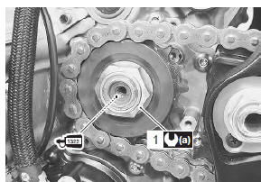
- Tighten the engine sprocket nut (1) to the specified torque.
Tightening torque engine sprocket nut (a): 145 n·m (14.5 Kgf-m, 105.0 Lbf-ft)
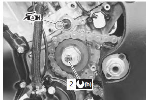
- Tighten the speed sensor rotor bolt (2) to the specified torque.
Tightening torque speed sensor rotor bolt (b): 28 n·m (2.8 Kgf-m, 20.0 Lbf-ft)
- Before installing the engine sprocket cover, apply a small quantity of grease to the clutch push rod.
 : Grease 99000–25010 (suzuki
super
grease “a” or equivalent)
- Install the engine sprocket cover (3).
- Tighten the speed sensor mounting bolt (4) to the specified torque.
Tightening torque speed sensor mounting bolt (c): 6.5 N·m (0.65 Kgf-m, 4.5 Lbf-ft)
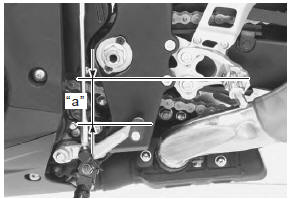
- Fit the gearshift link arm to the gearshift shaft so that the gearshift lever is located at height “a” below the footrest.
Gearshift lever height “a” standard: 65 – 75 mm (2.6 – 3.0 In)
- Adjust the drive chain slack. Refer to “drive chain inspection and adjustment” in section 0b (page 0b- 14).
 Drive chain related components
Drive chain
Engine sprocket
Rear sprocket
Dust seal
Bearing
Retainer
Sprocket mounting drum
Wheel damper
145 N·m (14.5 Kgf-m,
105.0 Lbf-ft ...
 Rear sprocket / rear sprocket mounting drum removal and installation
Removal
Remove the rear wheel assembly. Refer to “rear wheel assembly removal
and installation” in section 2d .
Loosen the rear sprocket nuts.
Draw out the rear sprocket mountin ...
Other materials:
Precautions
Precautions for engine electrical device
Refer to “general precautions” in section 00 (page 00-1) and “precautions for
electrical circuit service” in section 00
(page 00-2).
Component location
Engine electrical components location
Refer to “electrical components location” in section 0a .
Dia ...
Right handlebar
Engine stop switch 1
"" Position
The ignition circuit is off. The
engine cannot start or run.
"" Position
The ignition circuit is on and the
engine can run.
Front brake lever 2
Apply the front brake by squeezing
the front brake lever towards
the grip. The brake ligh ...
Inspection before riding
Warning
Failure to inspect and maintain
your motorcycle properly
increases the chance of an
accident or equipment damage.
Always perform a pre-ride
inspection before each ride.
Refer to the table on page 4-4
for check items. For further
details, refer to the inspec· ...