
Suzuki GSX-R 1000 Service Manual: Gearshift shaft oil seal / bearing removal and installation
Removal
- Remove the gearshift shaft. Refer to “gearshift shaft / gearshift cam plate removal and installation” .
- Remove the gearshift shaft oil seal (1).
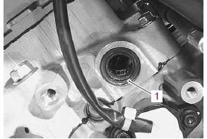
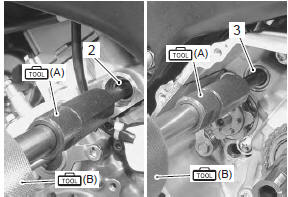
- Remove the bearings (2) and (3) with the special tools.
Special tool
 (a): 09921–20210 (bearing remover
(12
mm))
 (b): 09930–30104 (rotor remover
sliding
shaft)
Installation
Install the oil seal and bearing in the reverse order of removal. Pay attention to the following points:
| Caution the removed oil seal and bearings must be replaced with new ones. |
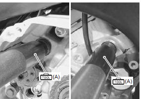
- Install the bearings with the special tool.
| Note the stamped mark side of gearshift shaft bearing faces outside. |
Special tool
 (a): 09913–70210 (bearing
installing set (10
– 75 Ô))
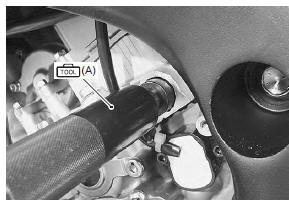
- Install the oil seal with the special tool.
Special tool
 (a): 09913–70210 (bearing
installing set (10
– 75 Ô))
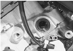
- Apply grease to the oil seal lip.
 : Grease 99000–25010 (suzuki
super
grease “a” or equivalent)
 Gearshift linkage inspection
Refer to “gearshift shaft / gearshift cam plate removal and installation” .
Gearshift shaft
Check the gearshift shaft for bend or wear.
Check the return spring for damage or fatigue.
If any de ...
 Specifications
Service data
Drive train
unit: mm (in) except ratio
Tightening torque specifications
Note
the specified tightening torque is described in the following.
“Transmission compon ...
Other materials:
Tp reset
When replacing the throttle body assembly or tp sensor
with a new one or reinstalling the tp sensor, reset the
tp learned value in the following procedures:
Note
keep the throttle valves fully closed while
resetting the tp learned value.
Turn the ignition switch on.
...
Isc valve preset and opening initialization
When removing or replacing the isc valve, set the isc
valve to the following procedures:
turn the ignition switch on.
Set up the sds tool. (Refer to the sds operation
manual for further details.)
Click the “active control”.
Click the “isc learned value reset” (1) ...
Specifications
Service data
Wattage
unit: w
Tightening torque specifications
Reference: for the tightening torque of fastener not specified in this
section, refer to “tightening torque list” in section 0c . ...