
Suzuki GSX-R 1000 Service Manual: Tp sensor adjustment
Inspect the tp sensor setting position and adjust it if necessary in the following procedures:
- connect the special tool (mode select switch) to the dealer mode coupler. Refer to “self-diagnostic procedures” in section 1a .
Special tool
 : 09930–82720 (mode selection switch)
- Warn up the engine and keep it running in idling speed.
- Turn the mode select switch on.
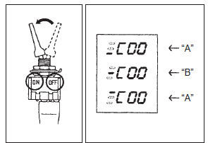
- Check the position of the bar in the left of c code displayed on the lcd panel.
|
- If the tp sensor adjustment is necessary, turn off the engine and lift up the throttle body from the intake pipes. Refer to “throttle body removal and installation” in section 1d .
- Loosen the tp sensor mounting screw using the special tool and turn the tp sensor to bring the bar to the correct position.
Special tool
: 09930–11950 (torx wrench (5 mm))
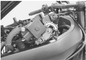
- Tighten the tp sensor mounting screw to the specified torque.
Tightening torque tp sensor mounting screw: 3.5 N·m (0.35 Kgfm, 2.5 Lbf-ft)
- Reinstall the throttle body.
- Turn on the engine and make sure that the tp sensor bar is at the correct position.
- Turn off the engine and reinstall the removed parts.
 Tp sensor removal and installation
Refer to “throttle body disassembly and assembly” in section 1d .
Removal
Remove the throttle body. Refer to “throttle body
removal and installation” in section 1d (page 1d-
10).
Remo ...
 Ect sensor removal and installation
Removal
Remove the left side cowling. Refer to “exterior parts removal and
installation” in section 9d .
Drain engine coolant. Refer to “cooling system inspection” in section
0b .
...
Other materials:
Storage procedure
If your motorcycle is to be left
unused for an extended period of
time, it needs special servicing
requiring appropriate materials,
equipment and skill. For this reason,
suzuki recommends that you
trust this maintenance work to
your suzuki dealer. If you wish to
service the machine for stora ...
Isc valve preset and opening initialization
When removing or replacing the isc valve, set the isc
valve to the following procedures:
turn the ignition switch on.
Set up the sds tool. (Refer to the sds operation
manual for further details.)
Click the “active control”.
Click the “isc learned value reset” (1) ...
Fuel pump disassembly and assembly
Disassembly
Remove the fuel tank. Refer to “fuel tank removal and installation” .
Remove the fuel pump assembly (1) by removing its
mounting bolts diagonally.
Spilled gasoline should be wipe off
immediately.
Keep away from fire or spark.
Work in a wel ...