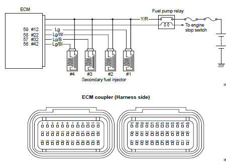
Suzuki GSX-R 1000 Service Manual: Dtc “c36” (p1764), “c37” (p1765), “c38” (p1766) or “c39” (p1767): secondary fuel injector circuit malfunction
Detected condition and possible cause
|
Detected condition |
Possible cause |
| Some failure exists in the fuel injector signal in a high load, high revolution condition. |
|
Wiring diagram
Troubleshooting
| Caution when using the multi-circuit tester, do not strongly touch the terminal of the ecm coupler with a needle pointed tester probe to prevent terminal damage. |
| Note after repairing the trouble, clear the dtc using sds tool. Refer to “use of sds diagnosis reset procedures” . |
|
Step |
Action |
Yes |
No |
|
|
1 |
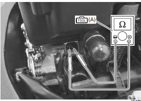
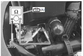
Special tool Tester knob indication resistance (Ω) Injector resistance 11 – 13 Ω at 20 °c (68 °f) (terminal – terminal)
Special tool Injector continuity ∞Ω¶ (infinity)
Are the resistance and continuity ok? |
Go to step 2. | Replace the injector with a new one. Refer to “throttle body disassembly and assembly” in section 1d . | |
|
2 |
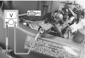
Special tool Tester knob indication
voltage ( Injector voltage battery voltage ((+) terminal: y/r – (–) terminal: ground)
Is the voltage ok? |
|
Open circuit in the y/r wire. |
 (a): 09900–25008 (multi
 )
)
 Dtc “c32” (p0201), “c33” (p0202), “c34” (p0203) or “c35” (p0204): primary
fuel injector circuit
malfunction
Dtc “c32” (p0201), “c33” (p0202), “c34” (p0203) or “c35” (p0204): primary
fuel injector circuit
malfunction
Detected condition and possible cause
Detected condition
Possible cause
Ckp signal is produced but fuel injector signal is
interrupted by 4 times or more continuity
...
 DTC “c40” (p0505 / p0506 / p0507): isc
valve circuit malfunction
DTC “c40” (p0505 / p0506 / p0507): isc
valve circuit malfunction
Detected condition and possible cause
Detected condition
Possible cause
C40/P0505
The circuit voltage of motor drive is
unusual.
Isc valve circuit open or ...
Other materials:
Windshield cleaning
Clean the windshield with soft
cloth and warm water with mild
detergent. If scratched, polish
with a commercially available
plastic polish. Replace the windshield
if it becomes scratched or
discolored so as to obstruct view.
When replacing the windshield,
use suzuki replacement windshield. ...
Special tools and equipment
Recommended service material
Note
required service material is also described in the following.
“Rear suspension components” “rear suspension assembly
construction”
Special tool
...
Dimmer / passing light switch inspection
Inspect the dimmer/passing light switch in the following
procedures:
remove the air cleaner box. Refer to “air cleaner box removal and
installation” in section 1d .
Disconnect the left handlebar switch coupler (1).
(Yellow)
Inspect the dimmer/passing light switch ...