Suzuki GSX-R 1000 Service Manual: Front fork removal and installation
| Note the right and left front forks are installed symmetrically and therefore the removal procedure for one side is the same as that for the other side. |
Removal
- Remove the front wheel. Refer to “front wheel assembly removal and installation” in section 2d .
Caution
|
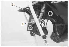
- Disconnect the brake hoses from the clamps on the front fender.
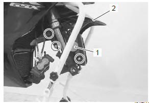
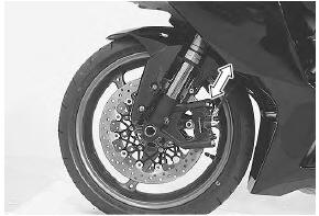
- Remove the reflex reflectors (1). (Except for e-02, 19, 51)
- remove the front fender (2) by removing the bolts
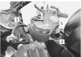
- Loosen the front fork upper clamp bolt (3).
- Loosen the handlebar clamp bolt (4).
| Note slightly loosen the front fork cap (5) to facilitate later disassembly. |
Special tool
 : 09941–53670 (front fork cap
socket
wrench (45 mm))
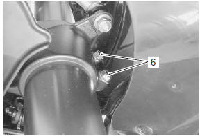
- Loosen the front fork lower clamp bolts (6) and remove the front fork.
| Note hold the front fork by hand to prevent it sliding out of the steering stem. |
Installation
- Set the front fork to the steering stem lower bracket temporarily by tightening the lower clamp bolts (1).
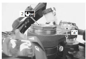
- Tighten the front fork cap (2) to the specified torque.
Tightening torque front fork cap (a): 35 n·m (3.5 Kgf-m, 25.5 Lbf-ft)
- Loosen the lower clamp bolts.
- Set the front fork with the edge of the outer tube positioned 7.0 Mm (0.28 In) “a” from the upper surface of the upper bracket.
|
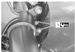
- Tighten the front fork lower clamp bolts (1).
Tightening torque front fork lower clamp bolt (b): 23 n·m (2.3 Kgfm, 16.5 Lbf-ft)
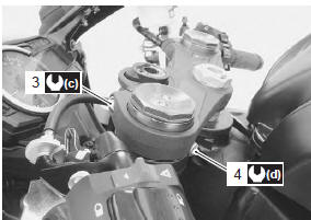
- Tighten the front fork upper clamp bolt (3).
Tightening torque front fork upper clamp bolt (c): 23 n·m (2.3 Kgfm, 16.5 Lbf-ft)
- Tighten the handlebar clamp bolt (4).
Tightening torque handlebar clamp bolt (d): 23 n·m (2.3 Kgf-m, 16.5 Lbf-ft)
- Install the front wheel. Refer to “front wheel assembly removal and installation” in section 2d .
 After After
remounting the brake calipers, pump the brake lever until the pistons push the pads correctly. |
| Note before tightening the front axle bolt and front axle pinch bolts, move the front fork up and down four or five times. |
 Front fork components
Front fork cap
O-ring
Rebound damping force adjuster rod
Compression damping force adjuster rod
Piston rod nut
O-ring
Piston ring
Rod guide case
Spr ...
 Front suspension adjustment
After installing the front fork, adjust the spring pre-load
and two kinds of damping force as follows:
Adjust the
left and right front forks to the
same setting.
Spring pre-load ...
Other materials:
Starter motor disassembly and assembly
Refer to “starter motor removal and installation” .
Disassembly
Disassemble the starter motor as shown in the starter motor components
diagram. Refer to “starter motor components” .
Assembly
Reassemble the starter motor in the reverse order of
removal. Pay attention to the following points:
...
Engine oil level check
Check the engine oil level as follows:
Place the motorcycle on level
ground on the side stand.
Start the engine and allow it to
idle for a few minutes.
Stop the engine and wait three
minutes.
Hold the motorcycle vertically
and check the oil level through
...
Front wheel related parts inspection
Refer to “front wheel assembly removal and installation” .
Tire
Refer to “tire inspection” in section 0b .
Front brake disc
Refer to “front brake disc inspection” in section 4b .
Dust seal
Inspect the lip of dust seals for wear or damage. If any
defects are found, replace the dust seal ...