Suzuki GSX-R 1000 Service Manual: Transmission installation
Install the transmission in the reverse order of removal.
Pay attention to the following points:
Bearing and oil seal
| Caution replace the removed bearings and oil seals with new ones. |
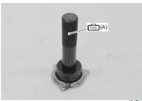
- Install the driveshaft left bearing oil seal into the retainer using the special tool.
Special tool
 (a): 09913–70210 (bearing
installing set (10
– 75 Ô))
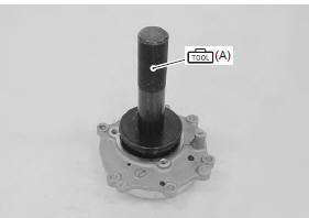
- Install the driveshaft left bearing with the special tool.
| Note the stamped mark side of the driveshaft left bearing faces outside. |
Special tool
(a):
09913–70210 (bearing installing set (10
– 75Ôö))
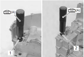
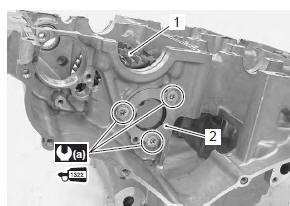
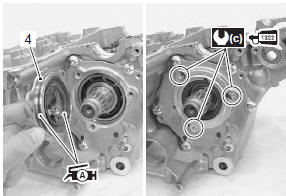
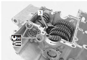
- Install the gearshift shaft bearings (1) and (2) with the special tool.
| Note the stamped mark side of the gearshift shaft bearing faces outside. |
Special tool
 (a): 09913–70210 (bearing
installing set (10
– 75 Ô))
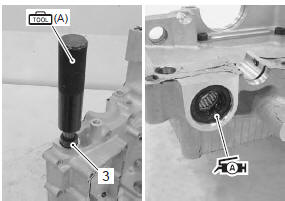
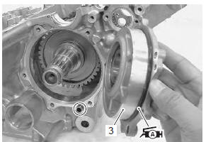
- Install the gearshift shaft oil seal (3) with the special tool.
Special tool
 (a): 09913–70210 (bearing
installing set (10
– 75 Ô))
- Apply grease to the oil seal lip.
 : Grease 99000–25010 (suzuki
super
grease “a” or equivalent)
- Install the gearshift cam bearing with the special tool.
Special tool
 (a): 09913–70210 (bearing
installing set (10
– 75 Ô))
Driveshaft assembly
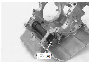
- Put the driveshaft assembly (1) into the lower crankcase.
- Install the driveshaft right bearing assembly (2).
- Apply thread lock to the bolts and tighten them to the specified torque.
 : Thread lock cement
99000–32110
(thread lock cement super “1322” or
equivalent)
Tightening torque driveshaft right bearing case bolt (a): 12 n·m (1.2 Kgf-m, 8.7 Lbf-ft)
- Install the dowel pin.
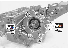
- Apply grease to the o-ring and install the driveshaft left bearing case (3).
| Caution replace the o-ring with a new one. |
 : Grease 99000–25010 (suzuki
super
grease “a” or equivalent)
- Apply thread lock to the bolts and tighten them to the specified torque.
 : Thread lock cement
99000–32110
(thread lock cement super “1322” or
equivalent)
Tightening torque driveshaft left bearing case bolt (b): 12 n·m (1.2 Kgf-m, 8.7 Lbf-ft)
- Apply grease to the oil seal lip and o-ring.
| Caution replace the o-ring with a new one. |
 : Grease 99000–25010 (suzuki
super
grease “a” or equivalent)
- Install the oil seal retainer (4).
- Apply thread lock to the screws and tighten them to the specified torque.
 : Thread lock cement
99000–32110
(thread lock cement super “1322” or
equivalent)
Tightening torque driveshaft oil seal retainer screw (c): 12 n·m (1.2 Kgf-m, 8.7 Lbf-ft)
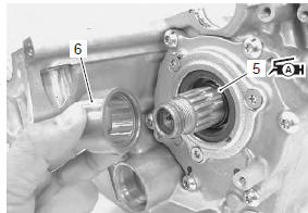
- Apply grease to the o-ring (5) and install it to the driveshaft.
| Caution replace the o-ring with a new one. |
: Grease 99000–25010 (suzuki
super
grease “a” or equivalent)
- Install the spacer (6).
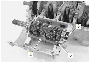
Gearshift cam and gearshift fork
- Install the gearshift forks (1) as shown.
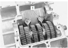
- Install the gearshift cam (2) with the bearing fitted.
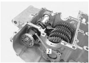
- With engaging each fork end to the cam groove, insert the fork shaft (3).
- Apply thread lock to the screws and tighten them to the specified torque.
 : Thread lock cement
99000–32110
(thread lock cement super “1322” or
equivalent)
Tightening torque gearshift cam bearing retainer screw (a): 10 n·m ( 1.0 Kgf-m, 7.0 Lbf-ft)
Countershaft
- Install the c-ring (1) and bearing pin (2) to the upper crankcase.
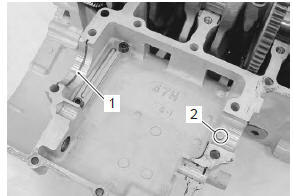
- Install the countershaft assembly to the upper crankcase.
| Note align the c-ring with the groove of bearing and the bearing pin with the indent on the bearing. |
- Turn the bearing and set the bearing dowel pin in position.
- Install the clutch push rod oil seal (3).
- Install the gearshift fork/gearshift shaft (4) and gearshift shaft plug (5).
 Transmission removal
Remove the engine assembly from the frame. Refer to “engine assembly
removal” in section 1d .
Remove the engine top side. Refer to “engine top side disassembly” in
section 1d .
&nbs ...
 Transmission construction
Countershaft
Driveshaft
...
Other materials:
Fuel mesh filter inspection and cleaning
Inspect the fuel mesh filter in the following procedures:
remove the fuel mesh filter. Refer to “fuel pump disassembly and
assembly” .
If the fuel mesh filter is clogged with foreign particles,
it hinders smooth gasoline flow resulting in loss of
engine power. Such a filter ...
Valve clearance inspection and adjustment
Inspect valve clearance
initially every 24 000 km (14 500 miles, 48 months)
Inspection
Valve clearance adjustment must be checked and
adjusted, a) at the time of periodic inspection, b) when
the valve mechanism is serviced, and c) when the
camshafts are removed for servicing.
Lift an ...
Cooling fan relay inspection
Inspect the fan relay in the following procedures:
remove the frame covers. Refer to “exterior parts
removal and installation” in section 9d (page 9d-
6).
Remove the cooling fan relay (1).
First check the insulation between “a” and “b”
terminals with tester. Then ap ...