Suzuki GSX-R 1000 Service Manual: General description
Combination meter system description
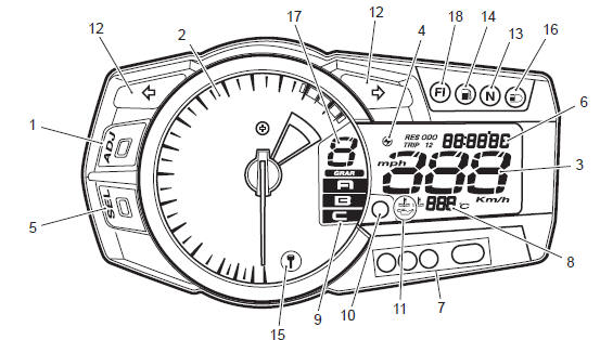
This combination meter mainly consists of a stepping motor, lcd (liquid crystal display) and leds (light emitting diode).
The tachometer pointer is driven by the stepping motor.
The lcds indicate followings: speed, odo / trip 1 / trip 2 / fuel reserve trip / clock / fi (dtc) / lap time counter / panel light brightness, gear position, engine rpm indicator, oil pressure indicator, engine coolant temperature and drive mode position.
Led (light emitting diode)
Led is used for the illumination light and each indicator light.
Led is maintenance free. Led is less power consuming and more resistant to vibration resistance compared to the bulb.
Engine rpm indicator light
This speedometer is equipped the engine revolution indicator light. The engine revolution indicator light is adjustable from 5 000 – 13 750 r/min. (From 5 000 r/min to 10 000 r/min, every 250 r/min and 10 000 r/min to 13 750 r/min, every 50 r/min: initial setting: 11 000 r/min)
|


Other materials:
Clutch installation
Install the primary driven gear assembly (1).
Caution
if it is difficult to install the primary driven
gear, rotate the crankshaft.
Be sure to engage the oil pump drive
sprocket with the primary driven gear.
Install the spacer (2) and bea ...
Spring pre-load adjustment
To change the spring pre-load,
turn the adjuster 1 clockwise or
counterclockwise. Turning the
adjuster clockwise will increase
the spring pre-load. Turning the
adjuster counterclockwise will
decrease the spring pre-load.
There are five grooved lines on
the side of the adjuster 1 for re ...
Oil jet removal and installation
Piston cooling oil jet
Removal
Remove the engine assembly. Refer to “engine assembly removal” in
section 1d .
Remove the crankshaft assembly. Refer to “engine
bottom side disassembly” in section 1d (page 1d-
49).
Remove the piston cooling oil jets (1) from the upper
cra ...