
Suzuki GSX-R 1000 Service Manual: Regulated voltage inspection
Inspect the regulated voltage in the following procedures:
- remove the front seat. Refer to “exterior parts removal and installation” in section 9d (page 9d- 6).
- Start the engine and keep it running at 5 000 r/min with the dimmer switch turned hi position.
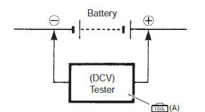
- Measure the dc voltage between the battery (+) and (–) terminals using the multi-circuit tester. If the voltage is not within the specified value, inspect the generator and regulator/rectifier. Refer to “generator inspection” and “regulator / rectifier inspection” .
| Note when making this test, be sure that the battery is in fully charged condition. |
Special tool
 (a): 09900–25008 (multi circuit
tester set)
Tester knob indication
voltage ( )
)
Regulated voltage (charging output) standard: 14.0 – 15.5 V at 5 000 r/min
- Install the front seat. Refer to “exterior parts removal and installation” in section 9d (page 9d- 6).
 Battery current leakage inspection
Inspect the battery current leakage in the following
procedures:
turn the ignition switch off.
Remove the front seat. Refer to “exterior parts
removal and installation” in section ...
 Generator inspection
Generator coil resistance
Remove the left side cowling. Refer to “exterior parts removal and
installation” in section 9d .
Disconnect the generator coupler (1).
Measure the re ...
Other materials:
Rear brake pad inspection
The extent of brake pads wear can be checked by observing the grooved limit
line “a” on the pads. When the wear exceeds the grooved limit line, replace the
pads with new ones. Refer to “rear brake pad replacement” .
Caution
replace the brake pad as a set, otherwise
braking performa ...
Precautions
Precautions for driveline / axle
Refer to “general precautions” in section 00 (page 00-1).
Never inspect or
adjust the drive chain while the engine is running.
Caution
do not use trichloroethylene, gasoline or such similar
solvent. These fluids will d ...
Speed sensor removal and installation
Removal
Remove the left side cowling. Refer to “exterior parts removal and
installation” in section 9d .
Disconnect the speed sensor lead wire coupler (1).
Remove the speed sensor (2).
Installation
Install the speed sensor in the reverse order of removal.
Pay atte ...