Suzuki GSX-R 1000 Service Manual: Clutch installation
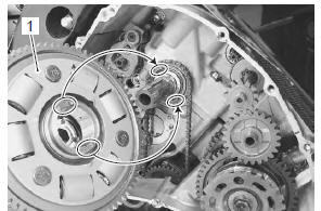
- Install the primary driven gear assembly (1).
Caution
|
- Install the spacer (2) and bearing (3), and apply engine oil to them.
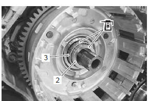
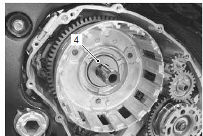
- Install the thrust washer (4).
- Install the seat washer (5) to the clutch sleeve hub (6).
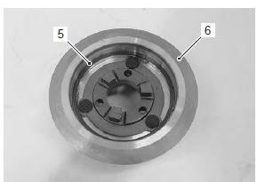
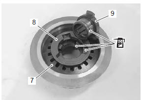
- Install the wave spring washers (7) and clutch lifter driven cam (8).
- Apply engine oil to the contacting surfaces of the clutch sleeve hub, clutch lifter drive cam and clutch lifter driven cam.
- Install the clutch lifter drive cam (9).
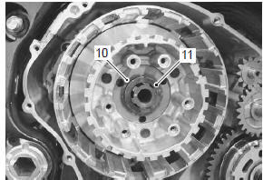
- Install the clutch sleeve hub, washer (10) and spring washer (11).
| Note the conical curve side of spring washer (11) faces outside. |
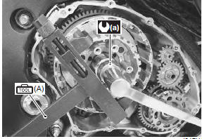
- Hold the clutch sleeve hub with the special tool.
Special tool
 (a): 09920–53740 (clutch sleeve hub
holder)
- Tighten the clutch sleeve hub nut to the specified torque.
Tightening torque clutch sleeve hub nut (a): 95 n·m (9.5 Kgf-m, 68.7 Lbf-ft)
- Lock the clutch sleeve hub nut with a center punch.
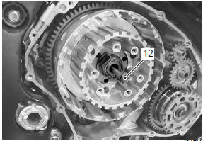
- Install the clutch push rod (12) into the countershaft.
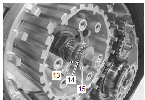
- Install the clutch push piece (13), bearing (14) and thrust washer (15) to the countershaft.
| Note thrust washer (15) is located between the pressure plate and bearing (14). |
- Install the spring washer seat (16) and spring washer (17) onto the clutch sleeve hub correctly.
- Apply engine oil to the clutch drive plates.
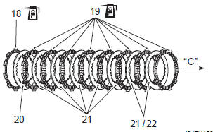
- Insert the clutch drive plates and driven plate one by one into the clutch sleeve hub in the prescribed order.
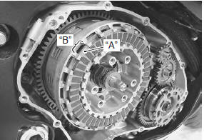
| Note insert the outermost no. 1 Drive plate claws “a” to the other slits “b” of clutch housing as shown in the figure. |
|
| Note two kinds of drive plate (no. 1 And no. 2) Are equipped in the clutch system, they can be distinguished by inside diameter. |
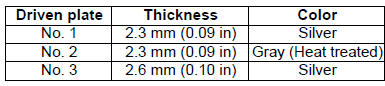
| Note three kinds of the driven plate (no. 1, No. 2 And no. 3) Are equipped in the clutch system, they can be distinguished by color and thickness. The no. 1, No. 2 And no. 3 Driven plates are 8 pcs. In total. 5 – 7 Pcs. Of no. 1 Driven plates are used with 1 pc. Of no. 2 And 0 – 2 pc(-s). Of no. 3 Driven plate(-s) as a set. The no. 3 Driven plate(-s) should be installed in pressure plate side. |
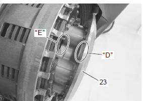
- Install the pressure plate (23).
| Note when install the pressure plate, fit the convex part “d” of the pressure plate onto the concave part “e” of the clutch sleeve hub. |
- Install the clutch springs and set bolts.
- Tighten the clutch spring set bolts to the specified torque.
Tightening torque clutch spring set bolt: 10 n·m (1.0 Kgf-m, 7.0 Lbfft)
| Note tighten the clutch spring set bolt little by little and diagonally. |
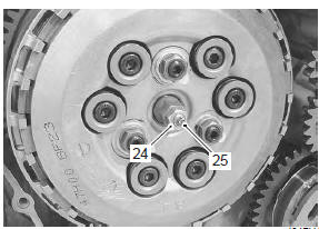
- Loosen the lock-nut (24) and turn in the clutch release adjusting screw (25) until resistance is felt.
- From that position, turn out the clutch release adjusting screw (25) 1 turn and tighten the lock-nut (24) while holding the screw (25).
Tightening torque clutch release adjusting screw lock-nut: 6 n·m ( 0.6 Kgf-m, 4.5 Lbf-ft)
- Apply bond lightly to the mating surfaces at the parting line between the upper and lower crankcases as shown in the figure.
 : Sealant 99000–31140 (suzuki
bond
no.1207B or equivalent)
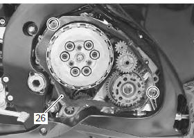
- Install the dowel pins and new gasket (26).
| Caution use new gasket to prevent oil leakage. |
- Apply bond lightly to the ckp sensor grommet.
 : Sealant 99000–31140 (suzuki
bond
no.1207B or equivalent)
- Apply molybdenum oil solution to the starter torque limiter/idle gear no. 2 Shaft holes.
M/o: molybdenum oil (molybdenum oil solution)
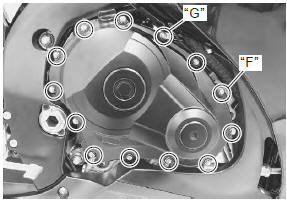
- Install the clutch cover and tighten the clutch cover bolts.
| Note fit new gasket washer to the bolt “f” and clamp to the bolt “g”. |
- Route the ckp sensor lead wire properly. Refer to “wiring harness routing diagram” in section 9a .
- ) Install the fuel tank. Refer to “fuel tank removal and installation” in section 1g .
- Pour engine oil. Refer to “engine oil and filter replacement” in section 0b .
 Clutch removal
Drain engine oil. Refer to “engine oil and filter replacement” in
section 0b .
Lift and support the fuel tank with the prop stay.
Refer to “fuel tank removal and installation” in secti ...
 Clutch parts inspection
Refer to “clutch removal” and “clutch installation” .
Clutch drive and driven plate
Note
wipe off the engine oil from the drive and
driven plates with a clean rag.
Measure t ...
Other materials:
Ignition switch
The ignitionr switch has 4 positions:
"Off" position
All electrical circuits are cut off.
The engine will not start. The key
can be removed.
"On" position
The ignition circuit is completed
and the engine can run. The
headlight and taillight will automatically
turn ...
Special tools and equipment
Recommended service material
Note
required service material is also described in the following.
“Front fork components”
Special tool
...
Steering damper maintenance
Keep the steering damper
shaft 1 clean at all times.
Wipe off any oil residue with a
cloth.
Do not confuse the grease-like
residue on the steering damper's
shaft with an oil leak. Collection of
this residue is normal and is from
oil seal lubricant used in the
damper.
Yo ...