Suzuki GSX-R 1000 Service Manual: Schematic and routing diagram
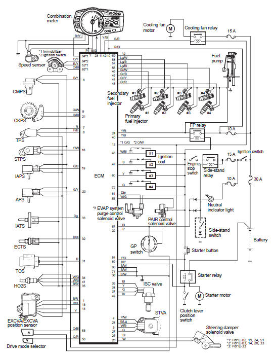
FI system wiring diagram
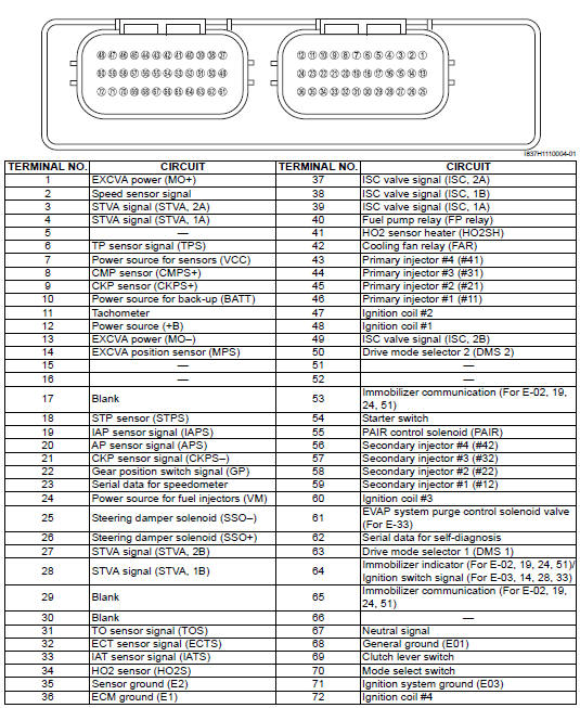
Terminal alignment of ecm coupler
 Self-diagnosis function
The self-diagnosis function is incorporated in the ecm. The function has two
modes, “user mode” and “dealer mode”.
The user can only be notified by the lcd (display) panel and led (fi indicator
...
 Component location
Fi system parts location
...
Other materials:
Cylinder head related parts inspection
Refer to “cylinder head disassembly and assembly” .
Cylinder head distortion
Decarbonize the combustion chambers.
Check the gasket surface of the cylinder head for
distortion. Use a straightedge and thickness gauge.
Take clearance readings at several places. If
readings exceed the ...
Clutch components
Clutch pressure plate
Clutch push piece
No. 1 Drive plate (8 pcs.)
No. 3 Driven plate (0 – 2 pcs.)
No. 1 Driven plate (5 – 7 pcs.)
No. 2 Driven plate (1 pc.)
No. 2 Drive plate (1 pc.)
Spring washer
Spring washer seat
Clutch sleeve hub
Seat ...
Dtc “c36” (p1764), “c37” (p1765), “c38” (p1766) or “c39” (p1767): secondary
fuel injector circuit
malfunction
Detected condition and possible cause
Detected condition
Possible cause
Some failure exists in the fuel injector signal in a high
load, high revolution condition.
Injector circuit open or short.
Injector malfunction.
Ecm malfunction.
...