Suzuki GSX-R 1000 Service Manual: Air bleeding from brake fluid circuit
Air trapped in the brake fluid circuit acts like a cushion to absorb a large proportion of the pressure developed by the master cylinder and thus interferes with the full braking performance of the brake caliper. The presence of air is indicated by “sponginess” of the brake lever and also by lack of braking force. Considering the danger to which such trapped air exposes the machine and rider, it is essential that after remounting the brake and restoring the brake system to the normal condition, the brake fluid circuit be purged of air in the following manner:
| Caution handle brake fluid with care: the fluid reacts chemically with paint, plastic, rubber materials, etc. |
Front brake
| Note if air is trapped in the master cylinder, bleed air from the master cylinder first in the same manner as follows. Refer to “front brake master cylinder assembly removal and installation” . |
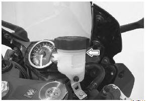
- Remove the reservoir cap and diaphragm.
- Fill the reservoir with brake fluid to the upper line of the reservoir. Place the reservoir cap to prevent dirt from entering.
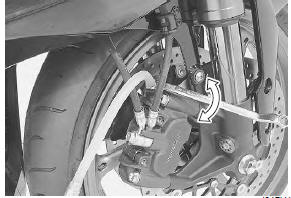
- Attach a hose to the air bleeder valve, and insert the free end of the hose into a receptacle.
- Squeeze and release the brake lever several times in rapid succession and squeeze the lever fully without releasing it.
- Loosen the air bleeder valve by turning it a quarter of a turn so that the brake fluid runs into the receptacle, this will remove the tension of the brake lever causing it to touch the handlebar grip.
- Close the air bleeder valve, pump and squeeze the lever, and open the valve.
- Repeat this process until the fluid flowing into the receptacle no longer contains air bubbles.
| Note while bleeding the brake system, replenish the brake fluid in the reservoir as necessary. Make sure that there is always some fluid visible in the reservoir. |
- Close the air bleeder valve and disconnect the hose.
Tightening torque air bleeder valve (front caliper): 7.5 N·m (0.75 Kgf-m, 5.5 Lbf-ft)
- Fill the reservoir with brake fluid to the upper line of the reservoir.
- Install the diaphragm and reservoir cap.
Rear brake
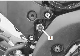
- Remove the right side frame cover. Refer to “exterior parts removal and installation” in section 9d .
- Remove the rear brake fluid reservoir mounting bolt (1).
- Remove the reservoir cap and diaphragm.
- Fill the reservoir with brake fluid to the upper line of the reservoir. Place the reservoir cap to prevent dirt from entering.
| Note the difference of bleeding operation from the front brake is that the rear master cylinder is actuated by a pedal. |
Tightening torque air bleeder valve (rear caliper): 6 n·m (0.6 Kgfm, 4.5 Lbf-ft)
- Fill the reservoir with brake fluid to the upper line of the reservoir.
- Install the diaphragm and reservoir cap.
- Install the removed parts.
 Rear brake light switch inspection and adjustment
Check the rear brake light switch so that the brake light
will come on just before pressure is felt when the brake
pedal is depressed. If the brake light switch adjustment
is necessary, turn the ad ...
 Brake fluid replacement
Caution
handle brake fluid with care: the fluid reacts
chemically with paint, plastic, rubber
materials, etc.
Front brake
Place the motorcycle on a level surface and keep the ...
Other materials:
Side stand
An interlock switch is provided to
cut off the ignition circuit when the
side stand is down and the transmission
is in any gear other than
neutral.
The side stand/ignition interlock
switch works as follows:
if the side stand is down and
the transmission is in gear, the
engine ...
Tire pressure and loading
Proper tire pressure and proper
tire loading are important factors.
Overloading your tires can lead to
tire failure and loss of vehicle control.
Check tire pressure each day
before you ride, and be sure the
pressure is correct for the vehicle
load according to the table below.
Tire pre ...
Clutch lever position switch inspection
Inspect the clutch lever position switch in the following
procedures:
disconnect the clutch lever position switch lead
wires (1).
Inspect the clutch lever position switch for continuity
with the tester.
If any abnormality is found, replace the switch with a
new one.
S ...