Suzuki GSX-R 1000 Service Manual: Brake fluid replacement
| Caution handle brake fluid with care: the fluid reacts chemically with paint, plastic, rubber materials, etc. |
Front brake
- Place the motorcycle on a level surface and keep the handlebars straight.
- Remove the brake fluid reservoir cap and diaphragm.
- Suck up the old brake fluid as much as possible.
- Fill the reservoir with new brake fluid.
Bf: brake fluid (dot 4)
- Connect a clear hose to the air bleeder valve and insert the other end of the hose into a receptacle.
- Loosen the air bleeder valve and pump the brake lever until the old brake fluid flows out of the brake system.
- Close the air bleeder valve and disconnect the clear hose.
Tightening torque air bleeder valve (front caliper): 7.5 N·m (0.75 Kgf-m, 5.5 Lbf-ft)
- Fill the reservoir with brake fluid to the upper mark of the reservoir.
- Bleed air from the brake fluid circuit. Refer to “air bleeding from brake fluid circuit” .
- Install the diaphragm and reservoir cap.
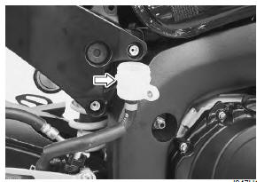
Rear brake
- Place the motorcycle on a level surface.
- Remove the right side frame cover. Refer to “exterior parts removal and installation” in section 9d .
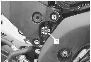
- Remove the rear brake fluid reservoir mounting bolt (1).
- Remove the brake fluid reservoir cap and diaphragm.
- Suck up the old brake fluid as much as possible.
- Fill the reservoir with new brake fluid.
Bf: brake fluid (dot 4)
- Connect a clear hose to the air bleeder valve and insert the other end of the hose into a receptacle.
- Loosen the air bleeder valve and pump the brake pedal until the old brake fluid flows out of the brake system.
- Close the air bleeder valve and disconnect the clear hose.
Tightening torque air bleeder valve (rear caliper): 6 n·m (0.6 Kgfm, 4.5 Lbf-ft)
- Fill the reservoir with brake fluid to the upper line of the reservoir.
- Bleed air from the brake fluid circuit. Refer to “air bleeding from brake fluid circuit” .
- Install the diaphragm and reservoir cap.
- Install the removed parts.
 Air bleeding from brake fluid circuit
Air trapped in the brake fluid circuit acts like a cushion to
absorb a large proportion of the pressure developed by
the master cylinder and thus interferes with the full
braking performance of the ...
 Front brake hose removal and installation
Removal
Drain brake fluid. Refer to “brake fluid replacement” .
2) Remove the front brake hoses as shown in the front brake hose routing
diagram. Refer to “front brake hose routing diagram” ...
Other materials:
Side-stand / ignition interlock system parts
inspection
Check the interlock system for proper operation. If the
interlock system does not operate properly, check each
component for damage or abnormalities. If any
abnormality is found, replace the component with a new
one.
Side-stand switch
Turn the ignition switch off.
Remove the left si ...
Special tools and equipment
Special tool
...
Transmission installation
Install the transmission in the reverse order of removal.
Pay attention to the following points:
Bearing and oil seal
Caution
replace the removed bearings and oil seals
with new ones.
Install the driveshaft left bearing oil seal into the
retainer using the special tool.
...