
Suzuki GSX-R 1000 Service Manual: Drive mode selector inspection
Inspect the drive mode selector in the following procedures:
- set up the sds tool. (Refer to the sds operation manual for further details.)
- Turn the ignition switch on.
- Click “data monitor”.
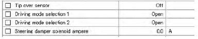
- Make sure each of “driving mode selection” on the monitor is indicated “open”.
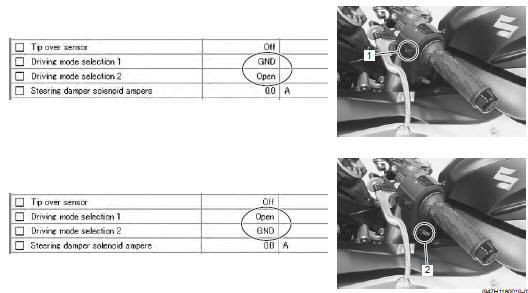
- Push each of drive mode selector (1) and (2). At this time, if the indication is changed to “gnd”, the function is normal.
 Ignition switch removal and installation
Removal
Remove the air cleaner box. Refer to “air cleaner box removal and
installation” in section 1d .
Disconnect the ignition switch lead wire coupler (1).
Disconnect the immo ...
 Specifications
Service data
Electrical
unit: mm (in)
Tightening torque specifications
Reference: for the tightening torque of fastener not specified in this
section, refer to “tightening torque list” i ...
Other materials:
Front brake master cylinder / brake lever disassembly and assembly
Refer to “front brake master cylinder assembly removal and installation” .
Disassembly
Remove the reservoir cap (1), plate (2), diaphragm
(3) and reservoir tank (4).
Remove the brake light switch (5) and brake lever
(6).
Remove the dust boot (7) and push rod (8).
...
Specifications
Tightening torque specifications
Note
the specified tightening torque is described in the following.
“Handlebar components” “steering components” “steering
damper construction”
Reference: for the tightening torque of fastener not specified in this
section ...
Battery runs down quickly
Troubleshooting
Step
Action
Yes
No
1
Check accessories which use excessive amounts of
electricity.
Are accessories being installed?
Remove accessories.
Go to step 2.
2
Check the battery for current leakage. Refer to “battery
cu ...