Suzuki GSX-R 1000 Service Manual: Ignition switch removal and installation
Removal
- Remove the air cleaner box. Refer to “air cleaner box removal and installation” in section 1d .
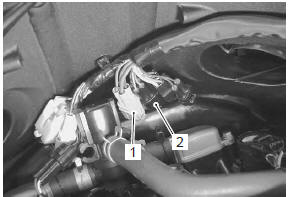
- Disconnect the ignition switch lead wire coupler (1).
- Disconnect the immobilizer lead wire coupler (2).
(For e-02, 19, 24, 51)
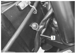
- Remove the harness clamp (3).
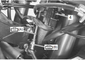
- Remove the ignition switch (4) with the special tools.
Special tool
 (a): 09930–11920 (torx bit (jt40h))
(b): 09930–11940 (torx bit holder)
(a): 09930–11920 (torx bit (jt40h))
(b): 09930–11940 (torx bit holder)
Installation
Install the ignition switch in the reverse order of removal.
Pay attention to the following points:
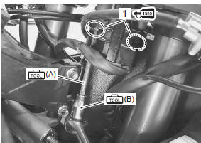
- tighten the ignition switch mounting bolts (1), right and left with the special tools.
| Caution when reusing the ignition switch bolts, clean the threaded part and apply a thread lock to them. |
Special tool
(a): 09930–11920 (torx bit (jt40h))
 (b): 09930–11940 (torx bit holder)
 : Thread lock cement
99000–32110
(thread lock cement super “1322” or
equivalent)
 Engine stop switch inspection
Inspect the engine stop switch in the following
procedures:
turn the ignition switch off.
Remove the air cleaner box. Refer to “air cleaner box removal and
installation” in secti ...
 Drive mode selector inspection
Inspect the drive mode selector in the following procedures:
set up the sds tool. (Refer to the sds operation manual for
further details.)
Turn the ignition switch on.
Cli ...
Other materials:
Clutch removal
Drain engine oil. Refer to “engine oil and filter replacement” in
section 0b .
Lift and support the fuel tank with the prop stay.
Refer to “fuel tank removal and installation” in section 1g .
Disconnect the ckp sensor coupler (1).
Remove the clutch cover (2).
...
Regulator / rectifier construction
Regulator/rectifier
Regulator/rectifier bracket
Air intake pipe (rh)
Spacer
Wiring harness
Connect
the regulator/rectifier couplers under the wiring harness
10
N·m (1.0 Kgf-m, 7.0 Lbf-ft)
...
Rear shock absorber inspection
Refer to “rear shock absorber removal and installation” .
Shock absorber
Inspect the rear shock absorber for damage and oil
leakage, and absorber bushing for wear and damage. If
any defect is found, replace the rear shock absorber with
a new one.
Caution
do not attempt to disassemble ...