Suzuki GSX-R 1000 Service Manual: Evaporative emission control system removal and installation (only for e-33)
Hose removal
- Lift and support the fuel tank. Refer to “fuel tank removal and installation” in section 1g (page 1g- 9).
- Remove the frame cover assembly. Refer to “exterior parts removal and installation” in section 9d .
- Remove the evap hoses as shown in the evap canister hose routing diagram. Refer to “pair system hose routing diagram” .
Installation
- Install the evap hoses as shown in the evap canister hose routing diagram. Refer to “evap canister hose routing diagram (only for e-33)” .
- Reinstall the removed parts.
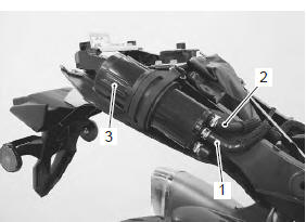
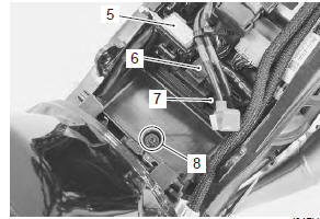
Evap canister removal
- Remove the frame cover assembly. Refer to “exterior parts removal and installation” in section 9d .
- Disconnect the surge hose (1) and purge hose (2).
- Remove the evap canister (3) from the bracket.
Installation
- Install the evap canister as shown in the evap canister hose routing diagram. Refer to “evap canister hose routing diagram (only for e-33)” .
- Reinstall the removed parts.
Evap system purge control solenoid valve removal
- Lift and support the fuel tank with the prop stay.
Refer to “fuel tank removal and installation” in section 1g .
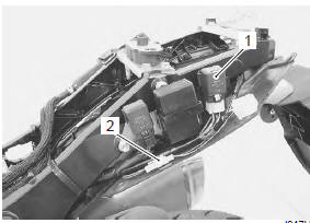
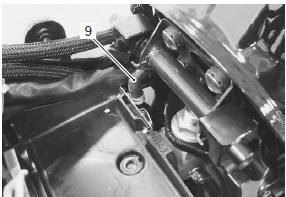
- Disconnect the coupler (1) and purge hoses (2).
- Remove the evap system purge control solenoid valve (3) with the bracket.
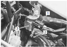
- Remove the evap system purge control solenoid valve from the bracket.
Installation
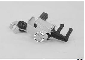
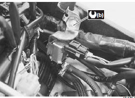
Install the evap system purge control solenoid valve in the reverse order of removal. Pay attention to the following point:
- tighten the evap system purge control solenoid valve mounting nut to the specified torque.
Tightening torque evap system purge control solenoid valve mounting nut (a): 6.5 N·m (0.65 Kgf-m, 4.5 Lbf-ft)
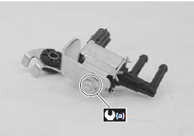
- Tighten the evap system purge control solenoid valve bracket bolt.
Tightening torque evap system purge control solenoid valve bracket bolt (b): 10 n·m (1.0 Kgf-m, 7.0 Lbf-ft)
Fuel shut-off valve removal
- Remove the front seat. Refer to “exterior parts removal and installation” in section 9d (page 9d- 6).
- Remove the battery. Refer to “battery removal and installation” in section 1j .
- Remove the ecm. Refer to “ecm removal and installation” in section 1c .
- Remove the frame cover assembly. Refer to “exterior parts removal and installation” in section 9d .
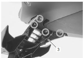
- Disconnect the cooling fan relay (1) from the rear fender (front).
- Disconnect the license plate light coupler (2).
- Remove the rear fender (rear) (3).
- Remove the battery mat (4).
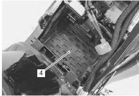
- Disconnect the fuse box (5), ap sensor (6) and to sensor (7) from the rear fender (front).
- Remove the rear fender (front) mounting bolt (8).
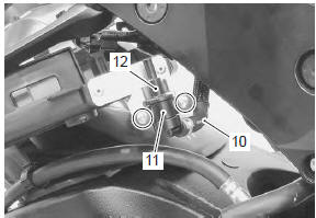
- Disconnect the surge hose (9).
- Move the rear fender (front) backward.
- Disconnect the surge hose (10).
- Remove the bracket (11) and fuel shaft-off valve (12).
Installation
Install the fuel shut-off valve in the reverse order of removal. Pay attention to the following point:
- install the fuel shut-off valve as shown in the evap canister hose routing diagram. Refer to “evap canister hose routing diagram (only for e-33)” .
 Crankcase breather (pcv) cover inspection
Inspect the crankcase breather (pcv) cover in the
following procedures:
remove the crankcase breather (pcv) cover. Refer to “crankcase breather
(pcv) hose / reed valve / cover removal an ...
 Evaporative emission control system
inspection (only for e-33)
Evaporative emission control system
inspection (only for e-33)
Refer to “evaporative emission control system removal and installation (only
for e-33)” .
Hose
Inspect the hoses for wear or damage. If it is worn or
damage, replace the hose with a new one.
...
Other materials:
Fuel line inspection
Inspect fuel line
every 6 000 km (4 000 miles, 12 months)
Inspect the fuel line in the following procedures:
lift and support the fuel tank. Refer to “fuel tank
removal and installation” in section 1g (page 1g-
9).
Inspect the fuel feed hose (1) for damage and fuel
leakage. ...
Fastener removal and installation
Type a
Removal
Depress the head of fastener center piece (1).
Pull out the fastener (2).
Installation
Let the center piece stick out toward the head so that
the pawls “a” closes.
Insert the fastener into the installation hole.
Note
to prevent the pawl ...
Engine assembly installation
Install the engine in the reverse order of engine removal.
Pay attention to the following points:
before installing the engine, install the collars (1).
Before installing the engine, install the engine
mounting thrust adjusters (2).
Gradually raise the rear side of ...